Modern structural construction is based on reinforced concrete, which is the marriage between the tensile strength of steel and the compressive strength of concrete. The concrete reinforcement plan helps engineers and contractors produce detailed drawings so that the building structures are safe, long-lasting, and compliant with set codes.
The ability to read and develop a concrete reinforcement plan is an important skill posed to civil engineers, site supervisors, structural detailers, BIM modelers, and steel fixers. The communication medium between the design office and the construction site advises on the arrangement of the rebar position, bending, lapping, and tying to this end, such plans are utilized.
In this blog, we will walk you through what a concrete reinforcement plan is, how to make sense of symbols and notations, and how to make correct, ready-to-build concrete reinforcement drawings.
What Is a Concrete Reinforcement Plan?
A concrete reinforcement plan is a detailed set of construction drawings that describe the size, type, number, and location of steel reinforcement in concrete elements. It guarantees the custom fit of strength and serviceability demands of the structure, especially to bending, shear, torsion, and axial loads.
The concrete reinforcement plan typically includes:
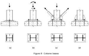
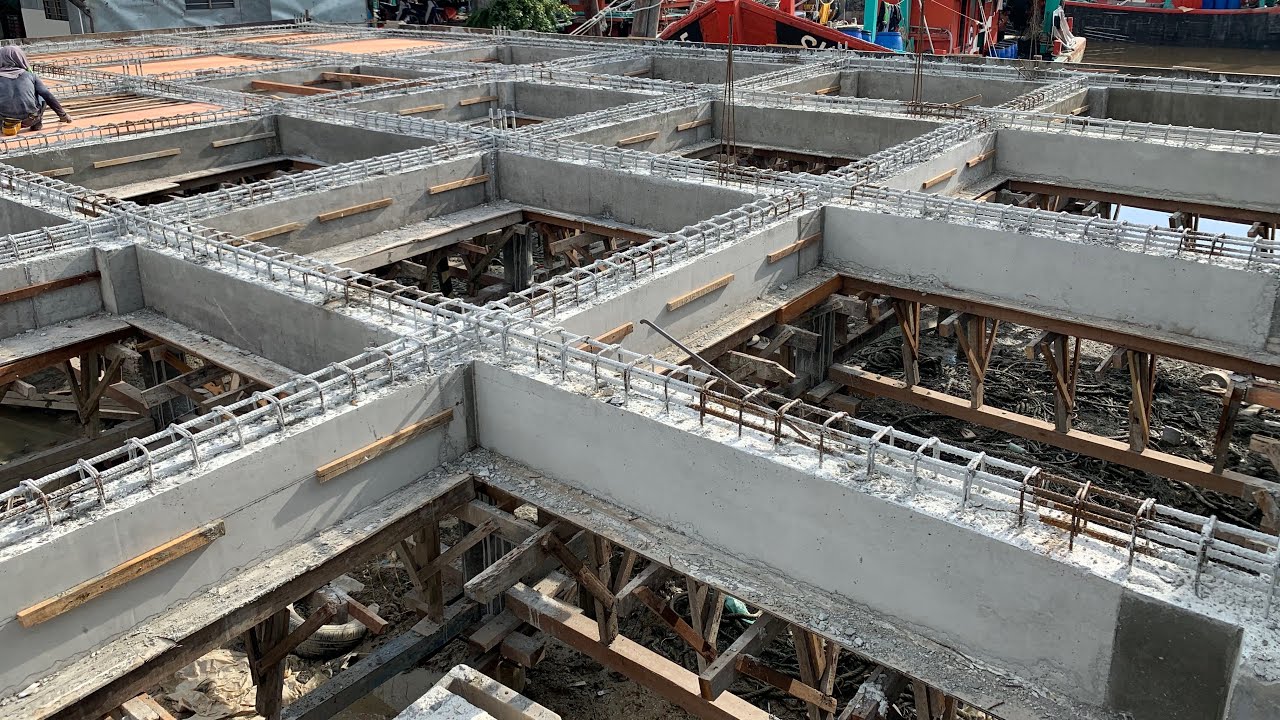
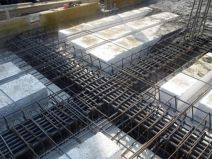
- Structural layouts showing the geometry of beams, columns, slabs, and footings
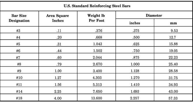
- Bar schedules indicating type, size, spacing, and total lengths of rebar
- Bending details with hook lengths, shapes, and angles
- Section views illustrating the exact location of top and bottom bars, stirrups, and ties
- Notes and standards specifying design codes, cover requirements, and lap splice lengths
Key Symbols and Notations Used in Reinforcement Drawings
To properly read or create a concrete reinforcement plan, one has to get acquainted with the most widely used symbols, abbreviations, and notations that are used across the drawings.
These are some of the most common conventions in a concrete reinforcement plan:
1. Bar Marks and Sizes
- Bar markings on bars usually consist of individual bar marks (e.g., B1, T2), that are used to reference bending schedules.
- The sizes can commonly be given numbers (e.g., #4 in imperial, T12 in metric), where the number is the diameter of the bar.
2. Spacing Notation
- Commonly represented as: @150mm c/c i.e. spacing of rebar is 150 mm center-to-center.
- Bar orientations are indicated (eg, EW (each way) or T/B (top and bottom).
3. Rebar Shape Codes
- The specifications of the bending of the bar are through shape codes of either U, L, or Z codes.
- The bar bending schedules have these shapes, which are supported by detailed angles and length.
4. Section and Callout Symbols
- Circular or rectangular section markers refer to specific drawing sections.
- Callouts (e.g., “See Detail A”) point to enlarged views for clarity.
5. Cover and Lap Notes
- Notations for concrete cover (e.g., “Cover = 40mm”) ensure corrosion protection and fire resistance.
- Lap splice notes indicate minimum overlap lengths when bars are extended.
6. Legends and General Notes
- A legend provides visual reference for all symbols used.
- General notes list reinforcement standards (e.g., ASTM A615, BS 8666) and placement instructions.
It is based on understanding these factors that there is an interpretation or establishment of a concrete reinforcement plan. Being able to master these details can help the teams to get construction right with fewer slips, less expensive mishaps, and in accordance with the design intention and the codes.
How to Read a Concrete Reinforcement Plan: Step-by-Step
It is not easy to read a concrete reinforcement plan without a method. It is not only about reading lines and symbols but also about interpreting the logic behind the layout and seeing how it applies to the on-site physical reinforcement.
A quick way of reading a concrete reinforcement plan includes:
A. Read the General Notes First
First, look at the general notes and legend sheet for the drawings. This contains some vital details like:
- Applications of design codes (ACI, BS, Eurocode etc)
- Concrete cover requirements
- Mat recycling – material specifications (e.g. Grade 60 steel)
- Length of lap splices and rules of placing
These notes establish the premise of looking at the motivation behind the concrete reinforcement scheme.
B. Understand the Structural Layout
Look at the structural, architectural plans, and the reinforcement drawings:
- Find grid lines, columns, slabs, and beams
- Find the section lines that give rise to specific reinforcement views
- Decide loading direction; the span of members
C. Identify Bar Sizes, Spacing, and Placement
Read the size, type, and spacing of rebar by using the bar schedule or callouts:
- Example: T12 @ 200mm c/c T/B T12 at 200mm center to center top and bottom
- Notice on bar orientation and the layer in which it is stacked (e.g. bottom, top, or middle)
D. Review Sections and Details
Sections give a three-dimensional understanding of the concrete reinforcement plan:
- Understand bar layering and how it changes at supports or midspans
- Check the hook lengths, anchorage zones, and development lengths
- Examine how stirrups are distributed in beams or how ties are spaced in columns
E. Interpret the Bending Schedule
The bending schedule tells you:
- Bar mark references (e.g., B01, B02)
- Shape codes and bend angles
- Lengths before and after bending
- Quantity and total weight
Together, these steps will help you visualize the physical steel layout that needs to be implemented on-site, reducing errors and improving construction accuracy.
Best Practices When Preparing a Concrete Reinforcement Plan
When designing an effective concrete reinforcement plan, a person should not think only about codes; by designing concretely, one should ensure safety, buildability, and material efficiency. It is at the detailing level that what you have designed comes to life, and therefore it is very important to have best practices.
1. Coordinate with Structural and Architectural Teams
Reinforcement drawings should correspond to the architectural details and the shape of the structure. In case of any transformation in the wall opening/slab recess, your concrete reinforcement plan should show the same to eliminate confrontations on site.
2. Avoid Rebar Congestion
Excessive overlapping of bars in a certain area, as well as in beams and columns, causes construction problems. Ensure that the spacing of bars is clear all along, and particularly, at intersections and hooks.
3. Use Clear, Consistent Notation
Write down fully all bar marks, dimensions, and shape codes. Confusion in a concrete reinforcement scheme may result in either a mistake in the factory or onsite work.
4. Include Bar Bending Schedules
Always put a list stipulating the details like length, type of bends, angles, and quantity of each bar as a bending schedule. This saves the time of steel fixers, and this brings uniformity.
5. Verify Cover and Lap Details
Detailing all the rebar (including concrete cover) should be made accordingly in terms of exposure to the environment and fire resistance. In addition, make the lap splicing position clear. It applies mostly in columns and slabs.
By applying these best practices, your concrete reinforcement plan will be both technically accurate and practically buildable.
Conclusion
A concrete reinforcement plan can be regarded as more than a series of drawings, which is both the heart of structural safety and constructive efficiency. Figuring out how to read and draw reinforcement drawings is imperative, whether you are a structural engineer designing the system, a drafter drawing the details, or a site foreman looking over the layout before it gets placed in place.
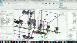
Understanding what a bar schedule and bend shape mean and how to coordinate the concrete reinforcement plan with MEP systems, knowing what to avoid, and having all these concepts covered enables construction professionals to develop high-quality structures that are code compliant and delivered on time and within budget.
Seek to simplify your workflow when doing reinforcement detailing? Take advantage of BIM software, network with your stakeholders early, and never forget to be clear and buildable in your designs.