Strand-Co specializes in delivering premium General Arrangement Drawings for construction engineering as well as industrial projects. Expert drawing services at our organization create accurate plans that boost project performance while minimizing errors. Strand-Co executes GA drawings for structures, mechanisms, and electricity while strictly adhering to industry specifications.
The General Arrangement Drawing (GA Drawing) thoroughly depicts how structures, systems, and components appear in their designed layout. The drawings present element relationships to serve as a clear guide for engineers, architects, and contractors while designing products or structures.
Our General Arrangement Drawing services at Strand-Co produce top-quality drawings that optimize both project efficiency and accuracy levels. Our company offers a customized approach for producing GA drawings to serve construction needs and industrial and MEP project requirements with assured execution efficiency. Your project needs expertly designed GA drawings to bring clear clarity to its development. Contact us immediately for a no-cost consultation or begin with a quote request today.
Strand-Co implements a controlled approach to provide customized, high-quality General Arrangement Drawing Services that respond to the specific needs of each project. Our efficient workflow guarantees precise delivery of projects that execute smoothly in various industries. The shop construction services support every phase from pre-fabrication planning to on-site execution. We help align stakeholders through visual clarity and technical precision.


The final delivery includes CAD and PDF formats together with other industry standard formats for approved GA drawings.

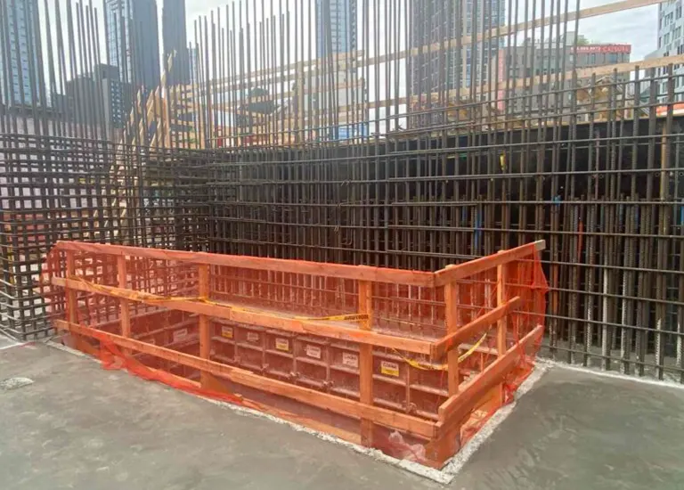
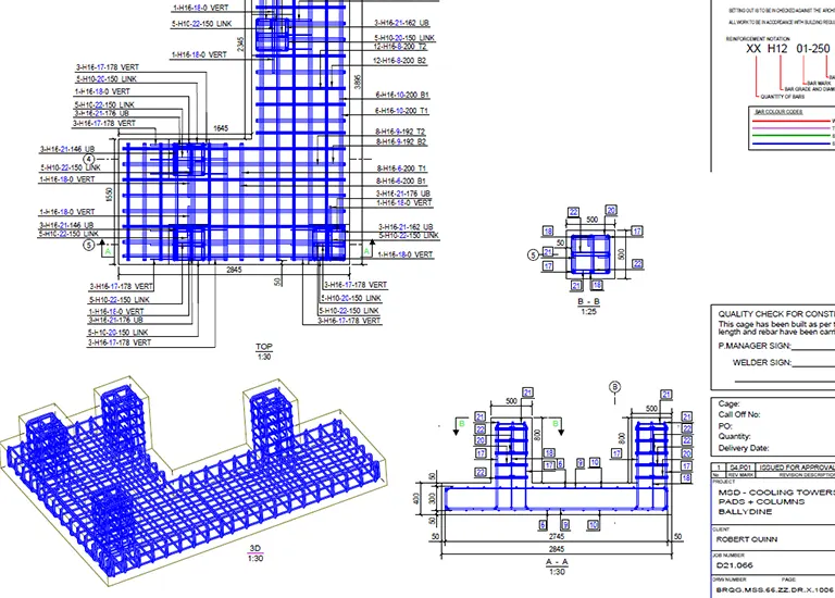
To streamline the rebar fabrication process, we create detailed rebar schedules and fabrication drawings. This ensures that the fabricated rebar elements align perfectly with the design intent.
Strand-Co functions as the industry-leading provider of drawing services with unique proficiency in GA drawings across multiple sectors.


GA drawings (General Arrangement drawings) provide a top-level view of a structure or system, illustrating dimensions, placements, and spatial coordination of different components.
A GA drawing shows the overall layout of a project, while a shop drawing provides detailed fabrication and assembly instructions for specific components.
General arrangement drawings display the positions, dimensions, and relationships of structural, mechanical, or architectural elements, helping teams understand the project layout.
If you’ve ever wondered what is GA in engineering, the answer is simple yet powerful—it stands for General Arrangement, the core drawing that defines the structural layout of any project. It shows the positioning, alignment, and interaction of every component, acting as the roadmap for construction.
At Strand Co, we go beyond simply answering what is GA in engineering—we perfect it. Our engineers and drafters use cutting-edge tools to produce GA drawings that enhance collaboration and eliminate ambiguity. Each plan we deliver ensures all project stakeholders—designers, fabricators, and site managers—are aligned from the start.
A Drawing GA (General Assembly Drawing) is essential for understanding the complete structure of an assembly. These drawings help engineers, technicians, and builders visualize complex assemblies before they move to production or construction.
In the world of construction, general arrangement drawing engineering serves as the foundation for design coordination and execution. Strand-Co focuses on providing detailed and industry-compliant General Arrangement Drawing solutions designed for the construction and manufacturing industries and MEP and industrial projects. Let us provide clear, precise, and fully annotated GA drawings that bring clarity and efficiency to your workflows.
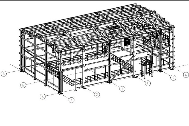
Drawing structural GA represents the initial construction basis since it shows full representations of buildings’ framework structures, which include steel components and concrete elements together with reinforcement plans. Through these drawings, architects, together with engineers and construction teams, receive accurate structural information, which prevents mistakes and maintains compliance with necessary standards.
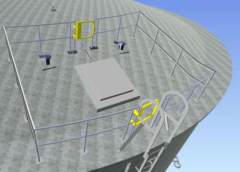
We create GA drawings for industrial and mechanical projects that describe how machinery and piping systems and ducts and critical components should be positioned to maximize efficiency in space. The services deliver precise equipment placement together with optimized pipe and duct networks that successfully merge with all structural and MEP components. Plus, every general arrangement drawing engineering plan includes dimensions, levels, and reference points.
MEP and electrical system GA drawings from our company help designers and project builders create accurate plans for electrical wiring alongside lighting fixtures and HVAC and plumbing pathways. The project design functions properly when we supply whole electrical circuit layouts together with structured HVAC and plumbing schematics that help all components fit perfectly.
Understanding the GA drawing full form helps teams align design and execution effectively. When precision is non-negotiable, dimensional drawings from Strand Co ensure every component fits exactly as intended. Our dimensional drafting services include detailed measurements, tolerances, and specifications critical for fabrication and assembly. Whether it’s a machine part or an architectural detail, we focus on delivering accurate dimensional drawings that meet ISO, ANSI, and project-specific standards. Get the drawings you need to build with confidence and compliance.
Industrial plants and factories rely on our GA drawing services to optimize operational efficiency by strategically arranging equipment and implementing smooth material flow pathways. Our detailed GAD drawings help businesses optimize space utilization, enhance productivity, and improve workplace safety.
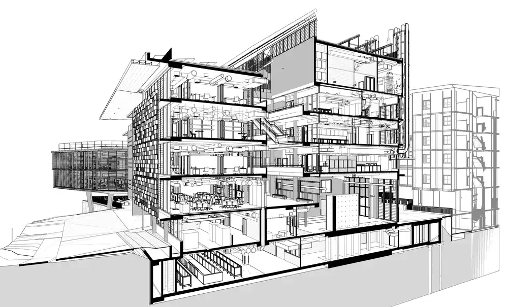
We integrate general arrangement drawings into Building Information Modeling (BIM) workflows, enabling seamless collaboration between multiple disciplines. Our BIM-based GA drawings improve project visualization, enhance clash detection, and streamline documentation management.
Our company provides custom GA drawing services that deliver solutions according to industry requirements and project complexity needs. Flexible solutions from our services enable clients to receive GA drawings in DWG, PDF, DGN, and Revit formats, which guarantee seamless integration into their existing workflow processes. Plus, our workshop drawings offer fabrication-level information for manufacturers and shop floors.
Strand Co offers General Assembly drawing services that illustrate the complete configuration of machinery, piping layouts, HVAC systems, and structural assemblies. We ensure that every connection, bolt, and alignment is accounted for.
Our G.A drawing (General Assembly) services offer a comprehensive depiction of your design in its entirety. Whether you’re dealing with mechanical systems, construction structures, or equipment layouts, we produce G.A drawings that outline component placement, orientation, and dimensions.
Every structural GA drawing includes detailed information about beams, columns, and supports. Each drawing is prepared by skilled draftsmen using advanced CAD and BIM software. With Strand Co, you’ll receive detailed general drawings that improve coordination and reduce on-site errors.
At Strand-Co, we provide General Arrangement Drawing Services across a diverse range of industries, ensuring high precision and compliance with industry-specific standards. Our expertise extends to construction, industrial manufacturing, shipbuilding, infrastructure, and more.
Strand Co specializes in delivering precise structural GA drawing packages for complex structures.
Construction drawings are essential to present architectural layouts and structural systems and elevation plans for your project while offering insufficient details regarding specific construction aspects such as shop drawings. The next stage consists of producing shop drawings.
Our experts’ shop drawings provide complete details of fabrication specifics alongside measurement data with selection choices and installation protocols. Through these drawings, all project components, such as steel beams, HVAC systems, and custom millwork, will be precisely manufactured and installed.
The shop drawing services of Strand Co. establish a design-construction connection that detects and prevents expensive mistakes and minimizes reconstruction work to enhance team communication between architects, engineers, and contractors.
At Strand Co, we know that clear and accurate drawings are the foundation of successful engineering and construction projects. Whether you need General Assembly (GA) drawings, dimensional drawings, or arrangement drawings, our expert team delivers with speed, accuracy, and attention to detail.
Professional GA drawing services ensure your structural layouts are accurate and easy to interpret. Don’t leave critical layouts and assemblies to chance—get technical drawings that speak your design language.


