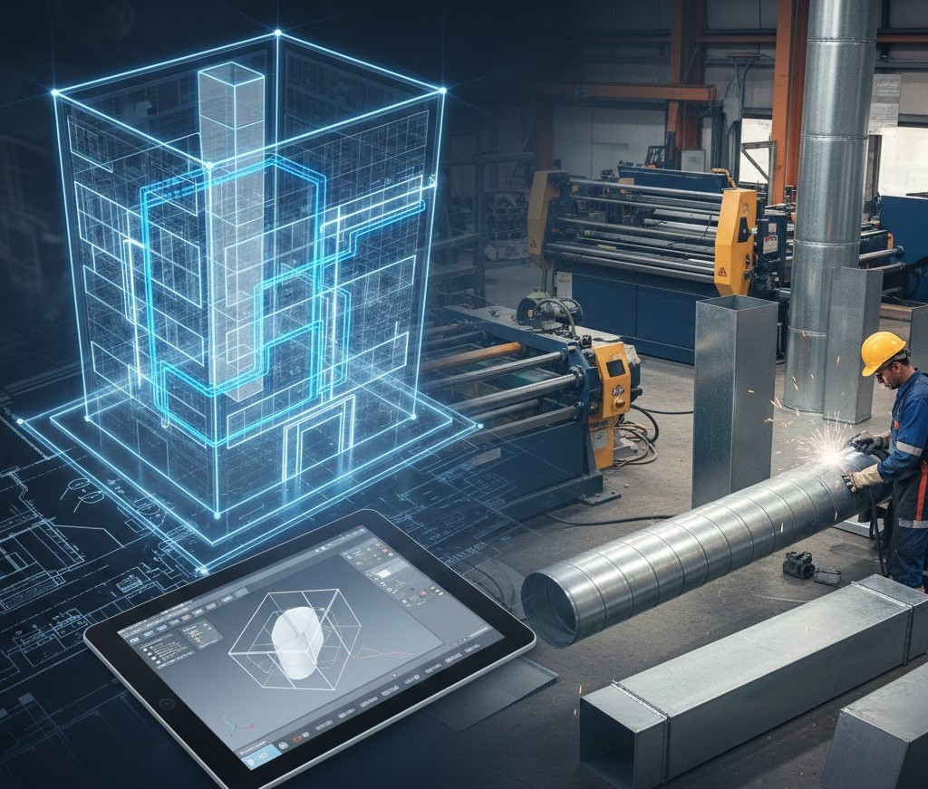
Designing and installing duct systems takes careful planning, precise measurements, and strong coordination across teams. In the past, most of this work was done manually, which led to delays, clashes on site, and installation errors. Today, Autodesk’s fabrication tools make the entire workflow smoother. They help designers, detailers, and fabrication shops work together from the very first model to the final manufactured duct piece.
This article explains the full ductwork lifecycle within Autodesk Fabrication, covering each phase from precise modeling to preparation for shop fabrication.
What Is Autodesk Fabrication?
Autodesk Fabrication is a set of software products used in the mechanical, electrical, and plumbing (MEP) industry to create accurate, build-ready models. It includes:
- Fabrication CADmep for detailed modeling
- Fabrication ESTmep for cost estimating
- Fabrication CAMduct for manufacturing and cutting patterns
Together, these tools help convert a digital design into real duct pieces that can be fabricated and installed on site.
Instead of relying on rough drawings or generic modeling, Autodesk Fabrication uses real-world content, including duct sizes, materials, connectors, thicknesses, and standards. This improves accuracy and reduces rework.

Why Fabrication Modeling Matters
Fabrication modeling is more than just drawing ducts. It ensures that what you see on the screen is exactly what will be built in the workshop.
With fabrication modeling, you create exact duct shapes, joints, and fittings. This helps prevent clashes with beams, pipes, and other building elements. Since the model matches real fabrication parts, installers receive accurate spools and sheets. This reduces cutting mistakes and material waste.
The model flows through estimating, planning, scheduling, and fabrication without repeating work. Accurate models help improve quantity takeoff and cost estimates. This leads to better budgeting and fewer surprises during construction.
Step 1: Starting the Model in CADmep
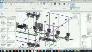
The workflow begins in Fabrication CADmep, an AutoCAD-based tool designed specifically for creating ductwork models that match real fabrication standards. Unlike generic drafting, CADmep uses actual parts, dimensions, and specifications that your fabrication shop can build without adjustment. This makes the model far more accurate and reduces issues later in the project.
Setting Up the Project
Before placing any ductwork, you first load a service template, which defines the technical requirements of your system. This setup includes:
- Material type, such as galvanized steel, stainless steel, or aluminum
- Sheet metal thickness and gauge
- Connector styles used for joints and seams
- Insulation material and thickness
- Standard fittings, elbows, transitions, and bend options
All of this information comes from the Fabrication content database, which usually follows SMACNA or local fabrication standards. Starting with the correct service setup ensures every part you place will follow shop-approved specifications, keeping the model consistent from the start.
Placing Ducts and Fittings
Modeling in CADmep feels familiar if you’ve used AutoCAD, but the parts behave much smartly. When you place a duct, CADmep automatically applies:
- The correct length for straight segments
- Proper connectors that match shop standards
- Required fittings such as transitions, elbows, offsets, or reducers
- Turning vanes for airflow when needed
Each piece “knows” how it should connect to other parts, which reduces manual adjustments. This saves a significant amount of time and ensures the model follows fabrication rules without constant checking.
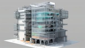
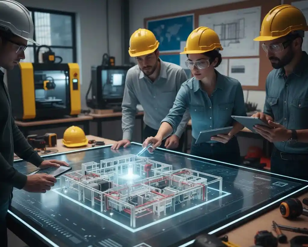
Using the 3D Model for Coordination
Since CADmep builds the duct system in full 3D, it becomes easier to coordinate with other trades. You can export the model to tools like Navisworks or Revit to perform clash detection. This step helps identify conflicts with beams, piping, electrical work, or architectural elements early in the design phase. Detecting these issues before construction prevents delays, rework, and costly changes on-site.
Step 2: Quality Checks and System Adjustments
Once the initial duct layout is complete in CADmep, the next stage is reviewing the model to make sure it meets technical, spatial, and fabrication requirements. Even with smart parts, a model always needs a detailed check before it moves further in the workflow.
Technical Review
The first review focuses on system performance. You look over the complete duct path to confirm that:
- Airflow direction aligns with design intent
- Duct sizes match the load calculations from the mechanical engineer
- Transitions are smooth enough to maintain airflow efficiency
- Pressure loss is minimized at fittings and bends
Checking Space and Clearance
A good duct layout must also fit comfortably within the building’s structure. You verify that:
- There is enough clearance between ducts and beams, ceilings, or walls
- Access is available for maintenance, cleaning, and fire dampers
- Equipment connections align correctly with air handling units or fans
- There is space for insulation thickness where required
This step helps avoid running into issues later in coordination meetings.
Clash Detection and Model Adjustments
Although CADmep handles fittings automatically, you may still encounter clashes with other trades. Using Navisworks or Revit for clash detection makes it easy to spot conflicts with:
- Structural beams
- Plumbing lines
- Cable trays
- Sprinkler piping
Once clashes are identified, you return to CADmep to adjust routes, raise or lower ducts, or insert offsets. The advantage is that CADmep updates connected components when you move a duct segment, so you don’t have to rebuild large sections manually.
Finalizing the Layout
Once all adjustments are complete, the duct system should be accurate, coordinated, and compatible with fabrication standards. This prepares it for the next stage, where you will divide the model into spools and convert it into shop-ready data.
Step 3: Preparing the Model for Fabrication
After the model has passed coordination checks and all adjustments are complete, the next stage is preparing it for the fabrication shop.
Breaking the System Into Spools
Spooling is one of the most important parts of the workflow. It divides the entire duct system into smaller, manageable sections that are easier to fabricate, transport, and install. Each spool usually represents a logical section of ductwork, such as:
- A complete run between two branches
- A vertical riser
- A section that fits on one pallet
- A portion that matches the installation sequence on site
Good spooling reduces confusion and helps the team install ducts in the correct order. It also ensures that each spool can physically be handled by the shop and the field crew.
Labeling and Identification
Every duct piece in the model receives a unique identity. This includes:
- Part numbers
- Size information
- Material and gauge
- Connector type
- Insulation requirements
- Spool number
These labels appear automatically on reports, spooling sheets, and fabrication drawings. When the parts arrive at the job site, installers can simply match each piece with its corresponding number, making the process more organized.
Applying Fabrication Rules
Fabrication shops follow specific rules when producing duct sections. These rules vary from shop to shop, but usually include:
- Maximum length of straight duct before adding a connector
- Preferred seam types for specific duct sizes
- Reinforcement requirements
- Standard flange types and hole patterns
- Minimum and maximum fitting angles
CADmep uses these rules to ensure every part in the model meets the shop’s standards.
Generating Reports and Sheets
Before sending the model to fabrication, CADmep generates several helpful reports, such as:
- Spool drawings
- Material lists
- Cutting summaries
- Connector schedules
- Insulation takeoffs
These documents help both the fabrication shop and the site team prepare for production and installation.
Final Model Review
The prepared model is reviewed once more to confirm that:
- All parts are assigned to spools
- Tags and labels are correct
- Fabrication rules have been followed
- There are no missing connectors or insulation notes
- All components have proper part numbers
This final check ensures the model is ready to be transferred into the fabrication environment without issues.
Step 4: Using CAMduct to Create Cutting Patterns
Once the duct model is fully prepared in CADmep, the next stage is to transfer it into CAMduct, which is the software used for generating precise cutting patterns.
Importing the Model
You begin by importing the spooled CADmep model into CAMduct. Since both programs share the same Fabrication database, all materials, gauges, connectors, and seams remain intact. This consistency is important because it removes the need for manual re-entry of information and reduces the chance of errors.
During import, the software organizes all duct parts by type, size, and spool number. This makes it easy for the shop team to identify which pieces belong to which section of the project.
Generating Cutting Patterns
CAMduct’s main function is to create machine-ready cutting patterns for sheet metal. These patterns include:
- Straight duct sections
- Elbows and transitions
- Offsets and reducers
- Radius pieces
- End caps and specialty fittings
The software calculates notching, seam allowances, and fold lines automatically. This helps ensure that once the metal is cut and formed, the pieces fit together correctly without additional trimming.
Optimizing Sheet Layout
Material efficiency is a major advantage of CAMduct. Before sending patterns to a plasma table or coil line, the software arranges pieces on sheet metal in the most efficient way possible. This process is known as nesting and helps the shop:
- Reduce scrap and material waste
- Maximize the use of each sheet
- Lower project cost
- Speed up production
Adding Labels and Markings
Each cut piece includes identification markings that match the spooling information from CADmep. These markings typically show:
- Part number
- Spool number
- Job name
- Connector type
- Insulation requirement, if applicable
Clear labeling keeps the workshop organized and makes installation easier because every piece can be traced back to its exact location in the building.
Machine Output
After the cutting patterns are complete, CAMduct sends the files to various machines used in the fabrication shop, such as:
- Plasma cutters
- Laser cutters
- Waterjets
- Press brakes
- Coil lines
The output includes all the data required for machines to cut, notch, and form the metal accurately. This reduces manual labor and ensures each piece matches the digital design.
Quality Control Checks
Before pieces move into production, many shops run a quick check within CAMduct to confirm:
- Gauges and materials match project requirements
- Patterns fit within the machine’s cutting area
- Connectors and seams follow shop standards
- Labels appear correctly on each piece
These checks help catch mistakes early, which saves time and prevents material loss.
Step 5: Fabrication and Workshop Assembly
Once the cutting patterns are ready in CAMduct, the next stage is fabrication in the workshop. This is where the digital model is transformed into physical ductwork that will eventually be installed on site.
Cutting and Forming
The fabrication shop begins by cutting the sheet metal according to the CAMduct patterns. Depending on the equipment available, this may involve:
- Plasma or laser cutting for straight sections and complex shapes
- Press brakes for forming bends and elbows
- Coil lines for continuous sheet fabrication
These machines follow the digital patterns precisely, ensuring every duct piece matches the dimensions specified in the model. Proper cutting and forming reduce errors, save time, and ensure a smooth assembly process.
Adding Fittings and Connectors
After cutting, the shop assembles each section by adding connectors, flanges, seams, or reinforcements as defined in the model. CAMduct ensures that each piece includes the correct type of connector and seam style, whether it’s a:
- Slip connection
- Flanged connection
- Pittsburgh seam
- S-lock seam
This automated approach ensures consistency across the project and minimizes manual modifications during assembly.
Insulation and Additional Finishes
If the duct requires insulation, the shop applies it according to the specifications from CADmep. Some projects also require additional finishes, such as:
- Protective coatings
- Acoustic lining
- Reinforcement for high-pressure sections
Applying these in the shop stage ensures that the ducts are ready for immediate installation, reducing labor on-site.
Quality Control in the Workshop
Fabrication shops use a set of standard quality checks to confirm each duct piece meets project requirements:
- Verify dimensions against the digital model
- Ensure connectors and seams are installed correctly
- Check alignment and angles of fittings
- Confirm labeling and spool numbers match the documentation
- Inspect insulation and finishes for consistency
These checks prevent mistakes from reaching the construction site and ensure smooth installation.
Packaging and Preparation for Delivery
Once fabrication is complete, the shop organizes and packages the duct sections according to spools. Each spool includes:
- All pieces belonging to that section
- Assembly instructions
- Labels and part numbers
- Any special handling requirements
Organized packaging ensures that installers can quickly identify, transport, and install the duct sections without confusion, keeping the project on schedule.
Step 6: Delivery and On-Site Installation

After fabrication is complete, the duct sections are ready to be delivered and installed on the construction site.
Organized Delivery
Duct sections are packaged according to their spool numbers. Each package includes:
- All duct pieces for that section
- Corresponding drawings or spool sheets
- Labels and part numbers matching the digital model
- Instructions for assembly and orientation
This organization ensures that installers can quickly identify each piece and place it in the correct position, reducing the risk of mistakes or delays.
Installation on Site
The installation team follows the spool sequence to assemble the ductwork. Because the pieces are fabricated and labeled precisely according to the model, they fit together without the need for on-site adjustments. Key installation checks include:
- Correct alignment with structural elements and mechanical equipment
- Proper connection to air handling units, fans, or other HVAC components
- Verification of clearances for maintenance and airflow
- Secure attachment of flanges, seams, and supports
This step ensures the duct system is installed as designed, maintaining efficiency and performance.
System Testing and Commissioning
Once installation is complete, the system undergoes testing to confirm it meets design requirements. Tests often include:
- Airflow measurements
- Pressure tests
- Leak detection
- Balancing of airflow through the system
If any adjustments are required, they can be made without major disruptions because the fabrication and installation followed the precise model.
Benefits of a Well-Executed Installation
When the workflow from CADmep to CAMduct is followed correctly, the benefits on-site are clear:
- Reduced installation time
- Fewer errors or rework
- Accurate alignment with other building systems
- Easier commissioning and maintenance
Following a structured, model-based approach ensures the project stays on schedule and maintains high-quality standards.
Common Mistakes to Avoid in Autodesk Fabrication Ductwork Workflow
Even with advanced tools, certain mistakes can slow down the workflow. Being aware of these pitfalls ensures smoother projects:
- Outdated Fabrication Database: Using old content may result in incorrect materials or connectors. Always update your database before starting a project.
- Skipping Coordination Checks: A perfect model can still clash with other systems if coordination is skipped. Run clash detection regularly.
- Ignoring Shop Standards: Every shop has its own preferences for seams, flanges, or duct lengths. Not aligning with these standards causes rework.
- Poor Spooling: Illogical spool divisions can confuse installers and create delays. Keep spools manageable and clear.
- Insufficient Labeling: Missing or unclear labels make it difficult for installers to identify parts, leading to errors on-site.
Conclusion
Autodesk Fabrication provides a complete solution for moving from ductwork design to shop-ready fabrication. By combining CADmep for modeling, CAMduct for pattern generation, and well-defined workflows, teams can reduce errors, save materials, and deliver projects on time.
From initial modeling to final installation, following a structured process ensures duct systems are accurate, coordinated, and ready for installation with minimal adjustments. Whether you are new to Autodesk Fabrication or looking to improve your workflow, understanding this process is key to achieving efficiency, quality, and consistency across every project.
FAQs
1. What is Autodesk Fabrication used for in ductwork projects?
Autodesk Fabrication is used to create accurate, build-ready duct models for MEP projects. It helps teams move from design to fabrication with real parts, precise measurements, coordinated layouts, and machine-ready patterns that reduce errors and keep installation smooth.
2. How does CADmep help in duct modeling?
CADmep lets detailers place real duct parts with the correct sizes, connectors, and fittings. The model follows fabrication rules, helps detect clashes, and produces clean spools for installation. This makes the duct layout more accurate and easier for shops to fabricate.
3. What is the role of CAMduct in the fabrication workflow?
CAMduct converts the duct model into cutting patterns for plasma tables, laser machines, or coil lines. It generates notching, seam details, and optimized sheet layouts. This reduces material waste and speeds up shop production by giving fabricators ready-to-cut patterns.
4. Why is spooling important for duct fabrication?
Spooling divides the duct system into manageable sections that can be fabricated, packed, and installed in sequence. It helps installers understand where each part goes, reduces confusion on site, and keeps the workflow organized from shop to field.
5. How do Autodesk Fabrication tools improve project accuracy?
The tools use real-world content and fabrication standards, which means every part in the model can be built. This improves estimating, reduces rework, supports better coordination, and gives fabricators clear instructions. Overall accuracy improves from design through installation.