In modern steel construction, the journey from design concept to physical structure relies heavily on precision, coordination, and technology. The steel detailing process is the key that connects the steel detailing to the 3D model of the structural engineer to the real steel that is built on site. Converting digital designs into real-world, fabricable designs and CNC readable files, project teams can automate the fabrication process, cut costs by errors, and enhance accuracy.
The steel detailing process has been streamlined to a highly automated and necessary concrete workflow with advanced software, including Tekla Structures and Autodesk Advance Steel, and inclusion of Computer Numerical Control (CNC) equipment. Knowledge of every stage of this process is critical to the engineers, fabricators and project managers with the objective of producing efficient and quality steel structures.
What Is Steel Detailing?
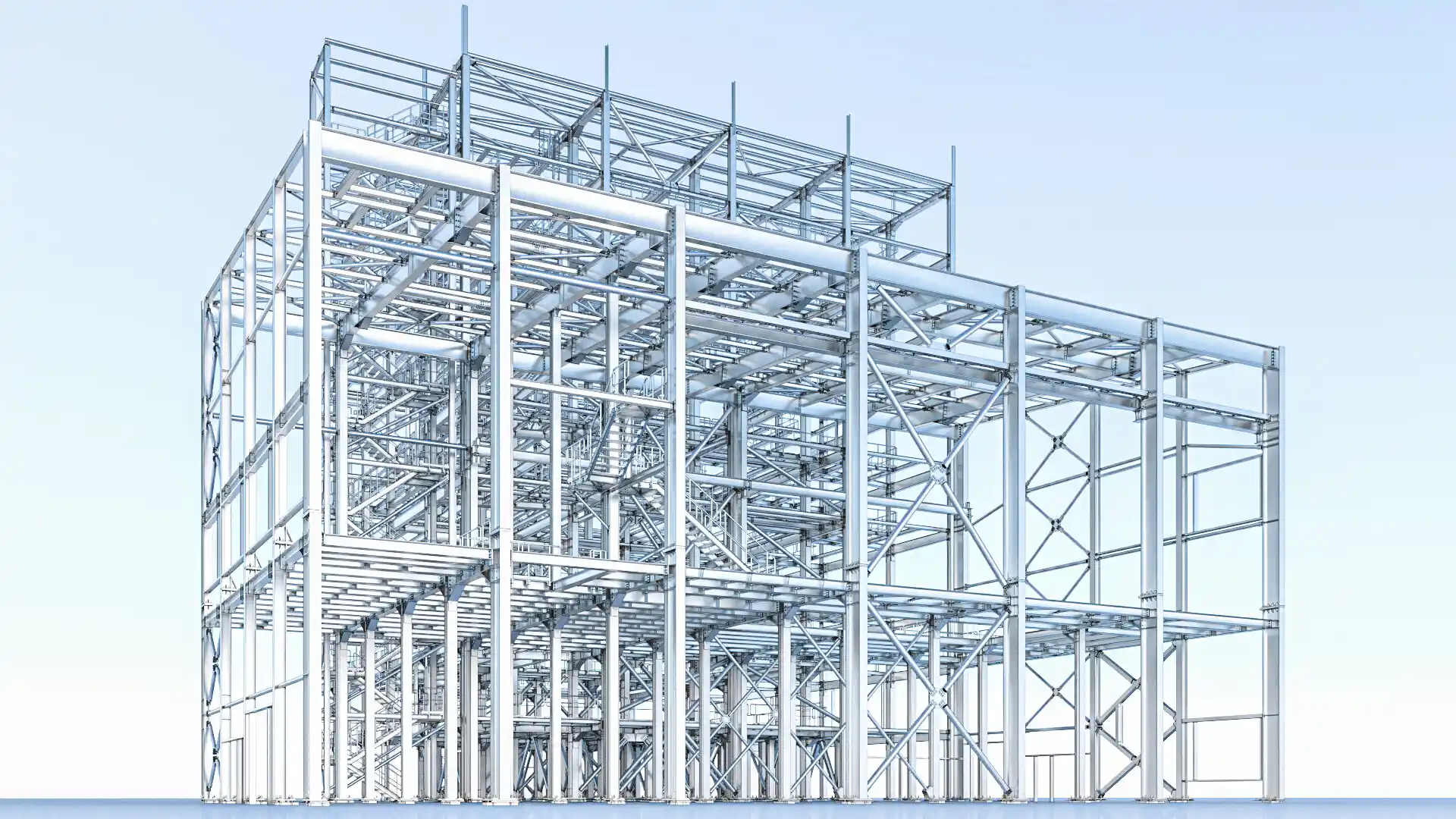
Steel detailing refers to the development of accurate drawings, three dimensional models and fabrication procedures of structural steel. These drawings communicate the intent of the engineer into buildable papers that are read and cut, welded, drilled and assembled by fabricators to build steel members.
Steel detailing typically includes:
- Beam, column, and brace member layouts
- Connection details, including bolts and welds
- Material specifications and grades
- Fabrication and erection notes
- Part numbering and assembly instructions
By bridging the gap between design and construction, steel detailing ensures that projects are built efficiently, safely, and according to specifications.
The Role of 3D Modeling in Steel Detailing
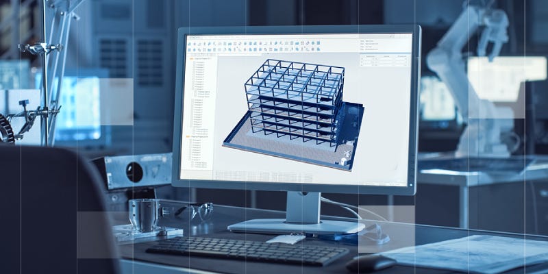
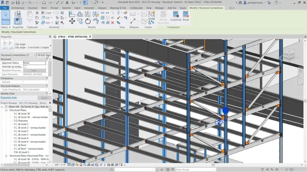
Modern steel detailing begins with a 3D model of the structure. Using Building Information Modeling (BIM) software like Tekla Structures or Autodesk Advance Steel, detailers create accurate, data-rich representations of every structural component.
Key Advantages of 3D Modeling:
- Clash Detection: Identify and resolve conflicts between structural, mechanical, and architectural systems before fabrication.
- Accurate Quantities: Generate material takeoffs and schedules with precision.
- Visualization: Provide engineers and contractors with a realistic view of the steel structure.
- Automated Drawings: Produce detailed shop drawings, connection details, and assembly instructions directly from the model.
The 3D model serves as the backbone for the entire detailing process, ensuring that every component is accurately represented and coordinated with other systems.
Creating Steel Shop Drawings from the 3D Model
Once the 3D model is finalized, the next step is generating steel shop drawings. These drawings provide fabricators with the information necessary to produce each component.
Essential Elements in Shop Drawings:
- Member Details: Dimensions, section types, and profiles for beams, columns, braces, and other members.
- Connections: Bolt sizes, weld types, and joint configurations following industry standards such as AISC.
- Fabrication Notes: Cutting lengths, hole locations, and welding instructions.
- Assembly Instructions: Piece marks, erection sequence, and alignment references.
High-quality shop drawings reduce the risk of errors on-site and ensure that steel components fit together correctly during assembly.
Translating Shop Drawings into CNC Files
Shop drawings now in place would mean that the design is shifted to the stages of fabrication using CNC machines. The computer numerical control (CNC) technology is used to automate the cutting, drilling and marking processes using accurate digital instructions.
CNC File Preparation Process:
- Exporting from 3D Model: The 3D model is exported to CNC-compatible file formats (e.g., DSTV, DXF, or NC files).
- Validation: CNC operators review files to ensure all cuts, holes, and welds match the design specifications.
- Machine Programming: CNC machines are programmed with the coordinates and instructions derived from the files.
- Fabrication Execution: Steel plates, beams, and sections are cut, drilled, and marked accurately, minimizing human error.
By converting shop drawings into CNC files, fabricators can achieve high precision, repeatability, and efficiency in production.
Benefits of Integrating 3D Modeling and CNC Fabrication
Combining 3D modeling with CNC fabrication brings significant advantages to the steel construction workflow:
- Precision: CNC machines cut and drill steel exactly as specified, reducing errors and material waste.
- Speed: Automated processes accelerate production compared to manual fabrication.
- Consistency: Each component is fabricated to the same high standard, ensuring seamless assembly.
- Cost Efficiency: Reduced rework and material waste result in lower overall project costs.
- Enhanced Coordination: Digital files ensure that shop drawings and fabrication instructions are perfectly aligned with the engineer’s intent.
The integration of these technologies ensures that the design-to-fabrication process is smooth, efficient, and reliable.
Common Challenges in the Steel Detailing Process
Some of the challenges that are normally encountered are data accuracy, compliance with industry requirements like AISC, file compatibility with the CNC machinery and coordination with other trades on complicated projects. Knowledge of those difficulties promises to help project teams to apply effective quality controlling strategies, facilitate the communication process, and see the fabrication and installation of steel parts as the first attempt.
While modern software and CNC technology have transformed steel detailing, several challenges still exist:
1. Data Accuracy
The 3D model may contain errors that will be passed on to shop drawings and CNC files and result in fabrication errors. The quality control needs to be attentive.
2. Coordination Between Teams
It is imperative that engineers, detailers, and fabricators liaise with each other. Errors in member sizes, connection details or material specifications can be brought on by a miscommunication.
3. File Compatibility
Various software and CNC machines can have a need to have certain file formats. To ensure that there are no delays, it is very important to make sure that there is compatibility.
4. Compliance with Standards
Any drawings and fabrication instructions should meet industry requirements including AISC of steel detailing. Failure to comply may lead to rejection or structural problems.
These challenges can be met at an earlier stage thus ensuring that the process of detailing and fabrication is efficient and of high quality.
Best Practices for a Smooth 3D-to-CNC Workflow
A smooth transition from 3D modeling to CNC fabrication is essential for achieving precision, efficiency, and quality in steel construction projects. Implementing best practices ensures that every step, from model creation to shop drawings to CNC file generation, is accurate, coordinated, and error-free.
To optimize the steel detailing process, follow these best practices:
- Maintain a Single Source of Truth: Ensure the 3D model is the master reference for all shop drawings and CNC files.
- Regular Quality Checks: Validate dimensions, connection details, and material specifications at each stage.
- Standardized File Formats: Use consistent CNC-compatible file formats to avoid machine errors.
- Early Coordination Meetings: Engage engineers, detailers, and fabricators early to align expectations.
- Software Training: Ensure detailers and operators are skilled in BIM software and CNC operations.
These practices help minimize errors, reduce rework, and improve overall project efficiency.
The Future of Steel Detailing: Automation and BIM Integration
The steel detailing process continues to evolve with advancements in automation, BIM integration, and cloud-based collaboration. Future trends include:
- Direct Model-to-Machine Fabrication: Fully automated workflows where 3D models feed CNC machines with minimal human intervention.
- Enhanced Clash Detection: AI-driven software to detect and resolve conflicts before fabrication.
- Real-Time Collaboration: Cloud platforms enabling engineers, detailers, and fabricators to update models and drawings instantly.
- Digital Twin Integration: Creating digital replicas of structures for long-term asset management and maintenance.
Adopting these innovations ensures higher precision, faster delivery, and smarter project management.
Conclusion
The transformation of a 3D model into CNC-ready files is one of the most significant advancements in modern steel detailing. This digital-to-fabrication process bridges the gap between engineering design and on-site manufacturing, ensuring every steel member is produced with exact precision, properly installed, and aligned perfectly with the structural needs of the project.
For builders, contractors, and fabricators in Hauppauge, NY, this level of accuracy has become essential. With advanced 3D modeling software, strict industry standards, and CNC-driven fabrication, steel components can be manufactured faster, cleaner, and with far fewer errors. The result is improved efficiency, reduced labor costs, and seamless coordination throughout the project lifecycle.
This streamlined workflow—starting from the digital model and ending with completed steel installation—ensures that steel buildings are delivered on time and within budget. It represents the future of modern steel construction: smooth, precise, and highly efficient.
Here in Long Island, Strand Consulting Corporation specializes in providing these advanced steel detailing solutions. As a trusted Steel Detailing Company, their team offers 3D modeling, CNC file generation, and project coordination services that support fabricators and contractors across the region.