Summary
The skyline across Nassau and Suffolk counties is shifting. Fast. New tall buildings keep popping up in places like Mineola, Garden City, Hempstead, and Bay Shore. And every single one of those towers depends on a very specific type of planning document called steel erection drawings. These drawings tell the ironworker crew exactly how to put the steel frame together. Piece by piece. Floor by floor. Skip them, and the whole project falls apart before it even starts. This article breaks down what these drawings actually contain, why this region makes them so tricky to produce, how they get made, which rules they must follow, and what every project team needs to know to stay on schedule and on budget. Companies like Strand Consulting Corporation have been helping contractors, fabricators, and structural engineers handle this exact kind of work for over 20 years.
Key Takeaways
- Steel erection drawings are step-by-step field instructions for ironworkers. They are completely separate from design drawings and shop drawings.
- Coastal winds, unpredictable soil, active rail lines nearby, and building departments with limited tall-building experience make Nassau and Suffolk county projects significantly harder than NYC ones.
- A full drawing package for a 20-story building can run anywhere from 80 to 150 sheets. That includes anchor bolts, floor framing plans, bracing frames, connection details, and erection sequence plans.
- The 2020 New York State Building Code, AISC 360, OSHA Subpart R, and the AISC Code of Standard Practice are the main rulebooks for how these drawings get made, reviewed, and used.
- New technology like 3D BIM models, cloud document tools, and QR codes on steel pieces are reshaping how drawings get delivered and used on job sites. Strand Consulting is already using these tools on real active projects.
Why Tall Buildings Need a Different Kind of Drawing
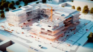
Most people picture floor plans and wall layouts when they think about construction drawings. That makes sense. But building a steel-framed high rise is a completely different animal. Before one column gets set or one bolt gets tightened, the ironworker crew has to know exactly where every single steel piece goes. How it connects to the pieces around it. And in what order the entire frame needs to go up.
That is exactly what steel erection drawings are for. They are the hands-on, field-level instructions for putting the structural skeleton of a building together. They are not the design drawings the structural engineer puts together to figure out loads and forces. They are also not the shop drawings the fabricator makes to show how pieces get cut and drilled at the factory. Steel erection drawings answer one specific question and one question only. How does this frame actually get built safely and correctly right there on the job site?
In Midtown Manhattan, this process runs like clockwork. Contractors, inspectors, and city officials handle tall steel buildings all the time. But the suburban counties sitting east of the city are a whole different story. And that difference changes almost everything about how these drawings have to be put together.
What Makes This Region So Much Harder to Build In
A few things make high-rise steel construction in Nassau and Suffolk counties tougher than other parts of the metro area. They are worth talking about one by one.
First up is the regulatory side. Local building departments out here just do not see high-rise steel construction every day. The New York City Department of Buildings reviews dozens of tall building projects every single year. Local offices in Nassau and Suffolk do not have that same daily exposure. So drawings submitted for a project in Mineola need extra notes, extra explanations, and extra clarity. You cannot assume the reviewer already knows what they are looking at. Firms that have been doing this work for years, like Strand Consulting Corporation out of Hauppauge NY, already know how to put together packages that keep local plan reviewers happy without a ton of back-and-forth.
Second is the wind. A huge portion of this region sits right up against the Atlantic Ocean or Long Island Sound. That means waterfront job sites face serious wind loads. And here is the part people often miss. A steel frame that is only halfway built is actually more vulnerable to wind than a finished building. The unfinished frame has not been tied into a rigid unit yet. So the drawings have to spell out exactly how temporary bracing gets installed at every single stage of the erection, just to keep the partially built structure standing.
Third is the ground itself. A lot of this area sits on sand, gravel, and glacial soil that changes dramatically from one block to the next. Tall buildings here often need deep foundation systems like driven piles or drilled shafts to hit stable ground. And the drawings have to match perfectly with the foundation plans. The anchor bolts holding those first columns to the foundation need to land at exactly the right spot, at the right height, at the right angle. If a mistake shows up after the concrete is already poured, fixing it is going to cost a lot of money.
Fourth is the infrastructure situation. The Long Island Rail Road cuts right through Nassau County and deep into Suffolk County. A lot of the area’s new high-rise zones sit very close to active LIRR stations and live rail lines. That means crane picks, steel deliveries, and road closures all need to get coordinated with railroad authorities. The drawings have to show exactly where cranes can go and when deliveries can happen.
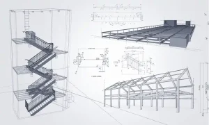
What a Full Drawing Package Actually Contains
A complete set of drawings for a high-rise in this region is a big document. A 20-story building can easily need between 80 and 150 individual sheets. The table below lays out the main categories and what each one is actually showing.
| Drawing Type | What It Shows |
| General Notes Sheet | Governing codes, steel grades, bolt types, weld standards |
| Anchor Bolt Plans | Column base locations, bolt size and depth, leveling requirements |
| Floor Framing Plans | All beams and columns at each floor, piece mark numbers, deck layout |
| Elevation and Bracing Frames | Vertical arrangement of columns, splice locations, brace connections |
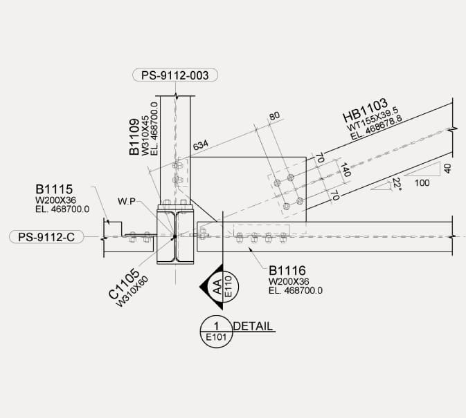
| Connection Details | Joint geometry, weld sizes, bolt patterns, gusset plate dimensions |
| Erection Sequence Plans | Order of steel placement, crane zones, temporary bracing locations |
Every drawing type has its own role to play. Anchor bolt plans are among the most critical ones in the whole package. An error in bolt placement that only shows up after the concrete is already set is a very expensive problem. Connection details are the most technically demanding because they have to show precisely how forces move from one member to the next. And erection sequence plans carry the biggest safety weight. They are the ones telling the crew how to keep the frame stable at every step of the way up.
How These Drawings Actually Get Made
The production process follows a clear path. Knowing that path helps owners and contractors build realistic project schedules.
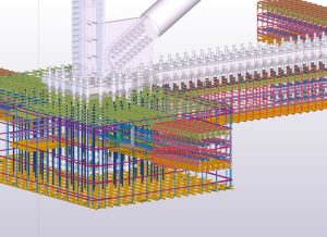
It all starts when the structural engineer of record wraps up the design documents. Those documents define the column grid, the member sizes, and the connection types. Once the steel contract is awarded, the fabricator’s detailing team builds a complete three-dimensional computer model of the steel frame. They typically use software like Tekla Structures or SDS/2 to do it. Strand Consulting Corporation works in both Tekla and Revit, which gives their clients a coordinated model that all the other trades on the project can actually use.
Both the shop drawings and the erection drawings come out of that model. The modeling and drawing production phase usually runs somewhere between 8 and 16 weeks on a high-rise job. After that, the full package goes to the structural engineer of record for review. The engineer checks that the drawings match the design intent, that the connection designs line up with the applicable standards, and that every required note and detail is actually there on the page.
Comments come back to the detailer. Corrections get made. The package gets resubmitted. A single review round typically takes 2 to 3 weeks, and it is very common to go through multiple rounds. In New York State, the structural engineer of record has to formally sign off on the drawings before they can be used on the job site.
The table below shows what a realistic production schedule looks like for a high-rise project in this region.
| Phase | Typical Duration |
| Structural engineer issues design documents | Week 0 |
| Fabricator prepares 3D model and first submission | Weeks 2 to 10 |
| Structural engineer review, Round 1 | Weeks 10 to 13 |
| Fabricator revisions and resubmission | Weeks 13 to 15 |
| Structural engineer review, Round 2 | Weeks 15 to 17 |
| Final approval and release for construction | Weeks 17 to 19 |
These timelines do not bend. Squeezing the review process to make up time lost somewhere else is almost always a bad idea. It creates bigger problems once the steel is in the air.
The Rules That Govern All of This
Every drawing package for a project in Nassau or Suffolk County has to comply with a specific set of codes and standards. The key ones are laid out in the table below.
| Standard | What It Covers |
| 2020 New York State Building Code | Overall design and construction requirements across New York State |
| AISC 360 | Design and fabrication of structural steel buildings |
| AISC 341 | Seismic design requirements for steel buildings in higher-risk zones |
| AWS D1.1 | Structural welding code governing weld quality and inspection |
| RCSC Specification | Installation and inspection of high-strength structural bolts |
| OSHA 29 CFR 1926 Subpart R | Worker safety rules specific to steel erection |
| AISC Code of Standard Practice | Defines the responsibilities of the engineer, fabricator, and erector |
The OSHA steel erection standard is worth singling out. It requires columns to be anchored by at least four anchor bolts. It requires columns to be plumbed within specific tolerances before work moves up to the next floor. And it requires safe landing areas to be in place for material deliveries. These are hard legal requirements. The drawings have to show how every single one of them gets met.
The AISC Code of Standard Practice is another big one. It makes clear that the erector, meaning the ironworking contractor, is responsible for the means and methods of putting the frame together. That includes temporary bracing. Unless the contract documents say something different. Project contracts need to be very specific about who owns that responsibility, especially on coastal sites where wind during erection is a serious concern.
Things Developers and General Contractors Really Should Know
For owners and project managers who did not go to school for structural engineering, the drawing process can feel like a lot. A few solid principles go a long way.
Bring the structural engineer of record into the process before the steel contract gets awarded. Getting expectations aligned early on the drawing review schedule saves a lot of headaches down the road. Require the steel fabricator to submit a real drawing production schedule with their bid. Not a rough estimate. Actual milestone dates.
Build real review time into the project schedule. Cutting corners on review to recover time is a false shortcut. It almost always blows up during erection when the fix costs far more than the time saved. And coordinate the structural drawings with the other trades early. Mechanical, electrical, and plumbing contractors need to get their pipes and ducts through the steel frame too. That coordination needs to happen while the drawings are still being made. Not after the steel is already standing.
On waterfront and coastal sites, temporary bracing for wind during erection needs to be a written contract requirement. It needs to show up in the erection sequence drawings. This is the thing that gets treated as an afterthought the most often. And it is also the thing that causes the biggest problems when it is not handled properly.
How Technology Is Changing the Way This Works
The process is shifting. Real projects across the region are already showing it.
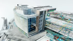
Three-dimensional BIM models are now standard at most major steel fabricators. These models do not just feed the drawing production process. They get shared with the architect, the mechanical contractors, and all the other trades so conflicts get caught before construction starts. Catching a beam that runs right through a duct run on a computer screen is a lot cheaper than catching it 15 floors up. Strand Consulting Corporation builds their Tekla and Revit models specifically to support that kind of clash-free coordination. Their teams have done it on high-profile projects all across the tristate area.
Paper drawings on the job site are slowly disappearing too. Ironworker crews on a growing number of projects now use tablets connected to cloud platforms like Procore or Autodesk Construction Cloud. Those platforms make sure the crew is always working from the most current approved revision of every sheet. Some fabricators are taking it one step further by putting QR codes directly on individual steel pieces. Scan the code and you go straight to the drawing sheet and connection detail for that exact member.
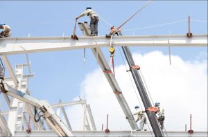
Prefabrication is picking up speed as well. Instead of picking beams and columns one at a time, some projects now bring in large pre-assembled steel modules to the site. These are sometimes called trees. Several members get combined into a single crane pick. Less work happens at height. That means a safer job site and usually a faster one too. It also means the erection drawings have to show how the modules are built and how they connect to each other once they are in the air.
One Last Thing Worth Saying
Every tall building starts as lines on a screen. A structural engineer’s vision of columns, beams, and connections that carry enormous loads safely for a hundred years or more. Steel erection drawings are what take that vision and turn it into real instructions. Instructions that a crew of ironworkers can actually follow on a freezing morning in January, hundreds of feet above the street.
Getting those drawings right is one of the best investments a project team can make. Complete. Coordinated. Code-compliant. And honest about the specific conditions on the actual site. The cost of a thorough, well-reviewed drawing package is tiny compared to the cost of one field problem that a better drawing would have stopped.
As this region keeps growing upward, the quality of the structural planning behind each new tower will decide how safe, efficient, and solid that growth actually turns out to be. Project teams that bring in experienced firms early, like Strand Consulting Corporation, with two decades of work in high-rise rebar detailing, structural BIM modeling, and shop drawings across Nassau, Suffolk, and the wider tristate area, are set up to get that planning right from the very first day.