Concrete masonry unit (CMU) is a common structural and non-structural wall building material because it is durable, non-combustible, and cheap to construct. CMU walls in seismic regions should be well designed to withstand the lateral forces and allow movement besides withstanding structural integrity during earthquakes. Bond beam detailing is one of the most important elements that allow such performance.
Bond beams are crucial in the distribution of loads, anchorage, and bonding of masonry walls to each other to form a single seismic-resistant structure. Inappropriate bond beam definition may result in cracking, wall separation, or disastrous destruction during an earthquake. This blog gives a detailed description of bond beam detailing of seismic Concrete masonry unit (CMU) walls, structural behavior, code, reinforcement strategies, construction considerations, and best practices.
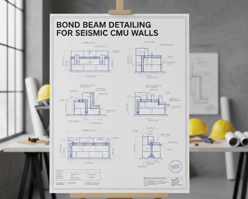
Bond Beams in CMU Construction
A bond beam is a horizontally reinforced concrete-filled CMU course, which is used to give strength and continuity across a masonry wall. It is usually composed of CMU blocks of special shapes, usually known as bond beam blocks, having knock-out webs or channel shapes enabling placement of continuity to horizontal reinforcement and grout placement.
Bond beams find use in seismic work where they serve as structural connector that holds vertical reinforcing steel together, relocates the lateral loads to the diaphragms and eliminates out of plane failures in walls. They combine a wet of many individual masonry units into a composite structure piece that has the ability to maintain complex load combinations.
Seismic Forces Acting on CMU Walls
CMU walls experience dynamic lateral forces in case of an earthquake due to the acceleration of the ground. These forces cause in-plane shear, flexural stressing and out-of-plane bending. Masonry walls are very susceptible to cracking and collapsing in absence of sufficient reinforcement and continuity.
Bond beams help address these challenges by:
- Distributing seismic forces evenly across wall segments
- Providing flexural capacity at critical elevations
- Tying wall sections to floors and roofs
- Anchoring diaphragms to vertical elements
Proper bond beam detailing ensures that seismic loads are transferred efficiently through the structure rather than concentrating stress at weak points.
Role of Bond Beams in Seismic Load Path Continuity
Structural performance during earthquakes must be provided with a clear seismic load path. Bond beams are also primary to forming this route, as they link the vertical reinforcement to the horizontal diaphragms and foundation systems.
Bond beams at floor and roof levels are collectors of diaphragm forces, which are carried into shear walls. The intermediate bond beams are used to curb cracking, prevent deflections, and keep the wall stable throughout the wall height. The reinforcement of bond beams is continuous so that they redistribute the load in case local damage takes place.
The absence of bond beams that are described well makes the seismic load path discontinuous, and therefore there is a high chance of structural failure.
Code Requirements for Seismic Bond Beam Detailing
Seismic bond beam detailing is governed by building codes such as:
- International Building Code (IBC)
- TMS 402/602 (Building Code Requirements for Masonry Structures)
- ACI 530
These codes specify minimum reinforcement sizes, spacing, anchorage lengths, and grout requirements based on seismic design categories. In higher seismic zones, codes typically require:
- Continuous bond beams at floor and roof levels
- Additional intermediate bond beams at prescribed vertical spacing
- Fully grouted cells at reinforced locations
- Adequate lap splices and development lengths
Compliance with these requirements is essential to achieve code-approved seismic performance.
Placement and Spacing of Bond Beams
The placement of bond beams in seismic CMU walls depends on wall height, seismic category, and structural function. Bond beams are commonly located at:
- Foundation level
- Floor and roof diaphragm connections
- Window and door lintels
- Intermediate heights to limit slenderness and cracking
In seismic zones, intermediate bond beams are often required at regular vertical intervals, typically ranging from 4 to 8 feet. Proper spacing reduces unsupported wall height and improves out-of-plane stability.
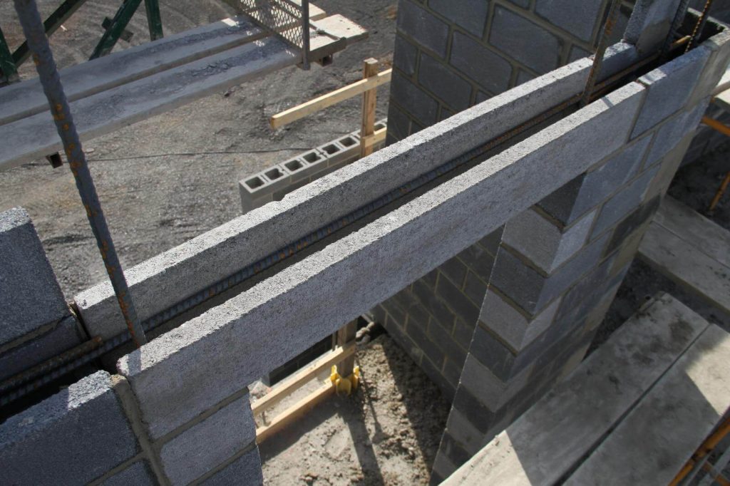
Reinforcement Detailing Within Bond Beams
Reinforcement detailing is critical to the performance of bond beams. Horizontal reinforcement typically consists of one or more continuous steel bars placed within the bond beam channel and fully embedded in grout.
Key detailing considerations include:
- Bar size selection based on seismic demand
- Continuous reinforcement with proper lap splices
- Adequate concrete cover for corrosion protection
- Proper anchorage into intersecting elements
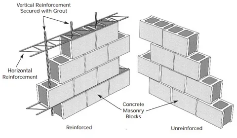
Vertical reinforcement must be securely tied into bond beams to create a continuous reinforcing system. This integration allows the wall to resist combined axial, shear, and flexural stresses during seismic loading.
Grouting and Construction Quality Control
Grouting is a fundamental aspect of bond beam performance. In seismic applications, bond beams must be fully grouted to ensure proper load transfer between reinforcement and masonry.
Poor grouting practices—such as voids, segregation, or insufficient consolidation—can severely reduce bond beam capacity. Quality control measures include:
- Using grout with appropriate flowability
- Proper placement and consolidation techniques
- Inspection of reinforcement placement before grouting
Attention to construction quality ensures that the engineered detailing translates into real-world performance.
Bond Beams at Openings and Discontinuities
Openings such as windows and doors introduce stress concentrations in CMU walls. Bond beams above openings serve as lintels, distributing loads around the opening while maintaining seismic continuity.
In seismic regions, lintel bond beams must be designed to:
- Support gravity loads
- Resist lateral seismic forces
- Anchor into adjacent wall segments
Proper detailing ensures that openings do not become failure points during seismic events.
Integration with Diaphragms and Foundations
Bond beams must be effectively integrated with floor and roof diaphragms to ensure force transfer. This typically involves:
- Embedding anchor bolts or straps
- Providing adequate development length for reinforcement
- Ensuring alignment between wall and diaphragm elements
At the foundation level, bond beams help distribute loads into the footing system and resist uplift forces generated during seismic activity.
BIM and Digital Detailing of Bond Beams
Modern BIM tools allow engineers to model bond beams with high accuracy, ensuring coordination with reinforcement, openings, and structural connections. BIM-based detailing improves clarity, reduces construction errors, and facilitates code compliance.
By visualizing bond beams in 3D, project teams can identify conflicts early and ensure proper reinforcement continuity across wall segments.
Best Practices for Seismic Bond Beam Design
Effective seismic bond beam design begins with a clear understanding of the seismic load path. Bond beams should be strategically placed to ensure continuous force transfer from diaphragms to vertical walls and down to the foundation.
Establish a Continuous Seismic Load Path
Successful seismic design starts with a clearly defined load path. Bond beams should be strategically located at roof and floor diaphragm levels, as well as at intermediate heights, to ensure lateral forces are efficiently transferred throughout the structure. This continuity reduces stress concentrations and improves overall wall performance.
Use Continuous Horizontal Reinforcement
Providing continuous horizontal reinforcement within bond beams improves ductility and allows seismic forces to redistribute across the wall system. Where splicing is required, lap lengths should meet or exceed code requirements and be positioned away from high-demand zones.
Properly Anchor Vertical Reinforcement into Bond Beams
Vertical bars should extend through bond beams with adequate development length or hooks to ensure full engagement. This creates a unified reinforcing system capable of resisting cyclic seismic loading and reducing the risk of brittle failure.
Design for Constructability and Clarity
Clear, consistent detailing improves construction accuracy. Standardizing bond beam block types, clearly indicating grout extents, and providing detailed reinforcement schedules help contractors execute the design correctly. BIM-based modeling can further enhance clarity by visually validating reinforcement continuity.
Conclusion
Bond beam detailing is a cornerstone of seismic CMU wall design. When properly engineered and constructed, bond beams provide continuity, strength, and ductility that allow masonry walls to withstand earthquake forces without catastrophic failure.
As seismic design standards continue to evolve, the importance of accurate detailing, quality construction, and coordinated workflows will only increase. By understanding and applying best practices for bond beam detailing, engineers and builders can deliver safer, more resilient CMU structures capable of performing under the most demanding seismic conditions.