There is a huge transition of the construction industry to the industrialised, off-site, and modular construction. The owners desire fast delivery, contractors with fewer site conflicts, and fabricator models they can rely on in order to manufacture accurately. The center of this change is LOD 400, which is the highest development level that is normally used prior to fabrication and assembly. In contrast to the schematic or design-intent models, LOD 400 models are fully detailed, dimensionally precise, and fabrication-ready geometry, with few possibilities of interpretation or guesswork.
With prefabrication, precision is savings. The less time is lost in re-work, RFIs, miscuts, and delays in installation, the more accurate the model is. This is where LOD 400 is the digital blueprint, which connects design and fabrication with highly coordinated, detailed, and production-ready information. This blog explores extensively what LOD 400 actually entails, what it offers to fabrication processes and why it has become the foundation of the contemporary construction industry.
What Is LOD 400? A Clear Definition
LOD 400 (Level of Development) is one of the most detailed BIM models, where the components of the building are defined using full fabrication, assembly, and construction information. The geometry in LOD 400 is accurate enough to be used in manufacturing, unlike in earlier LOD stages, where it was not accurate enough to allow a smooth transition between digital design and actual fabrication.
Key characteristics of LOD 400 include:
- Accurate dimensions, materials, and product specifications
- Detailed fabrication joints and connections
- Manufacturing tolerances and installation clearances
- Laser-accurate geometry for off-site or modular fabrication
- Information suitable for CNC machines, spool drawings, and shop drawings
- Exact locations of supports, hangers, penetrations, and welded/bolted points
Basically, LOD 400 removes the interpretation level of construction. Fabricators are informed precisely, installers are aware of the placement of the components and GCs have a model that one can rely on to facilitate effective sequencing.
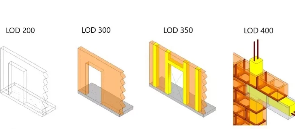
The Difference Between LOD 300, LOD 350, and LOD 400
Understanding LOD 400 requires context within the broader LOD spectrum.
LOD 300 – Design Intent
- Elements are accurately placed, but not fully detailed
- Used for coordination and visualization
- Does not contain fabrication-ready details
LOD 350 – Interface Coordination
- Connections to other trades are modeled
- Supports and penetrations appear
- Good for routing construction, but still insufficient for shop fabrication
LOD 400 – Fabrication Level Detail
- All fabrication details are modeled
- Dimensions, tolerances, and material specs included
- Ready for spool drawings and off-site production
This level of precision is what makes LOD 400 indispensable for MEP prefabrication, modular construction, structural steel fabrication, and facade manufacturing.
Why LOD 400 Is Essential for Prefabrication
As construction moves toward industrialization, prefabrication demands models that are not conceptual—they must be production-grade. LOD 400 plays several critical roles in this transition.
1. Accuracy for Manufacturing and CNC Production
Fabrication shops depend heavily on automation. Whether using pipe cutting machines, plasma cutters, CNC rebar benders, or welding robots, precision is non-negotiable.
LOD 400 models include:
- Exact pipe lengths
- Weld or groove requirements
- Cut angles
- Bolt patterns
- Prefab assembly breakdown
This eliminates manual measuring and reduces human error.
2. Reduced On-Site Labor and Faster Installation
When components arrive at the jobsite as complete assemblies, installation becomes plug-and-play.
With LOD 400, installers know:
- Exact hanger locations
- Routing heights
- Sleeve and penetration positions
- Assembly sequences
The result: rapid installation, fewer delays, and dramatically reduced field labor hours.
3. Improved Clash Detection and Spatial Coordination
Although clash detection is often associated with LOD 300 or 350, LOD 400 significantly enhances its reliability.
LOD 400 helps detect:
- Prefab module interferences
- Clearance issues around valves and access panels
- Fabrication constraints
- Conflicts with structural and architectural systems
Because the geometry is fabrication-level, clash results are more actionable.
4. Enhanced Schedule Certainty
Prefabrication thrives on predictability.
LOD 400 supports:
- Precise production planning
- JIT (Just-In-Time) delivery
- Accurate lead-time forecasting
- Reduced schedule slippage
In megaprojects, this can save months, especially for complex MEP systems.
5. Cost Control and Waste Reduction
Accurate shop drawings and fabrication-ready details minimize:
- Overordering of materials
- Fabrication rework
- Jobsite delays
- Costly design changes
LOD 400 ensures every piece is planned, measured, and prefabricated with minimal waste.
How LOD 400 Supports MEP Prefabrication
MEP systems—mechanical, electrical, and plumbing—are highly complex and require precise routing and coordination. LOD 400 provides the exact information fabricators need to prefabricate:
Mechanical Systems
- Ductwork
- HVAC modules
- Chilled and hot water piping
- VAV units and air-handling components
Plumbing Systems
- Sanitary and storm drainage
- Domestic water pipes
- Gas systems
- Preassembled plumbing racks
Electrical Systems
- Conduits
- Cable trays
- Prefab electrical rooms
- Bus ducts and risers
Fire Protection Systems
- Sprinkler systems
- Backflow assemblies
- Fire pump connections
All of these rely heavily on LOD 400 for accurate spool drawings, prefab assemblies, and field installation guidance.
How LOD 400 Drives Modular Construction
In modular and off-site construction, entire rooms or building sections are built in a factory and assembled on-site like LEGO blocks.
LOD 400 supports modularization by:
- Providing dimensioned models for module layou
- Ensuring tolerances fit manufacturing lines
- Coordinating building services inside modules
- Defining connection points between modules
- Ensuring modules fit into site-installed components
Without LOD 400, modular construction would be almost impossible.
LOD 400 in the BIM Workflow: A Step-by-Step Perspective
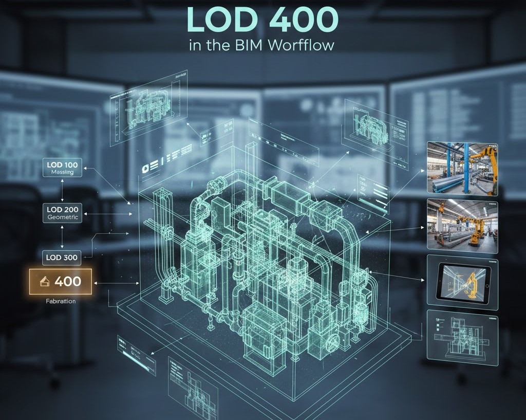
The introduction of LOD 400 in the BIM process can be seen as a step-by-step process, but the introduction is not the final step in the upstream decisions that determine the extent to which a project’s transition to fabrication is correct and efficient.
BIM maturity stage by stage provides the foundation of making fabrication-ready models, so that the construction teams, fabricators, and installers are operating off of accurate, coordinated, and clash-free data. The step-by-step analysis below explains the way LOD 400 will be made an integral part of a solid BIM procedure.
1. Begin with LOD 300 Design Coordination
The process begins with LOD 300 models, which designers use to specify the overall size, location, and building systems. During this phase, architects, engineers, and trade contractors will cooperate to ensure that the major aspects do not exceed the spatial limitations of the project. Even though geometry is not fabrication-ready, this step provides a dependable outline of the detailing to be done in later advanced stages.
2. Advance to LOD 350 Interface Modeling
Once the design intent is aligned, the model transitions to LOD 350. Here, modelers introduce interfaces, supports, and connections that define how building systems interact with surrounding components. MEP supports, hangers, structural connections, and penetration requirements are added to minimize surprises during downstream coordination. This stage builds the foundation needed for true fabrication detailing.
3. Develop LOD 400 Fabrication-Ready Geometry
At LOD 400, each component is modeled with exact dimensions, tolerances, and connection details. Modelers account for real-world manufacturing standards, such as fitting lengths, weld joints, bend radii, and assembly segmentation. This produces shop-ready geometry that can be converted into spool drawings and CNC machine inputs with minimal interpretation.
4. Generate Shop Drawings, Spools, and BOMs
With the LOD 400 model, the teams automatically create fabrication documentation, such as spool drawings, cut lists, and Bills of Materials. Such outputs direct production teams, which allows them to procure materials, minimize waste and simplify fabrication processes properly.
5. Enable CNC Integration and Off-Site Fabrication
LOD 400 geometry is fed directly to cutting tables, bending machines and robotic welders. Off-site manufacturing starts with trust, since the accuracy of the models makes the components to be produced to specifications and in the process eliminating the need to rework and make changes on-site.
6. Support Installation, QA/QC, and Field Verification
Finally, LOD 400 models guide on-site installation. Field crews use coordinated locations, hanger points, and assembly sequences for precise installation. Laser scanning or field verification ensures that the built environment matches the digital model, supporting a smooth transition to LOD 500 and long-term facility management.
Common Challenges in Producing LOD 400 Models
Despite their benefits, LOD 400 models are challenging to produce.
Typical obstacles include:
- Lack of Clear BIM Standards: Without a BIM Execution Plan (BEP) and LOD specification, teams produce inconsistent details.
- Insufficient Coordination Time: LOD 400 requires more detailing time compared to early-phase BIM.
- Interdisciplinary Misalignment: Sometimes trades work in silos, leading to conflicts during detailed modeling.
- Limited Fabrication Knowledge: Modelers must understand how components are made, not just how they look.
- Technology Gaps: Fabricators may lack software compatible with the BIM pipeline.
Conclusion
LOD 400 is the driver of modern prefabrication, as it allows contractors, designers, and fabricators to work more precisely, efficiently, and confidently. LOD 400 is the key to the utmost project assurance by eliminating waste and enhancing coordination to POC-friendly modular building and digital twins.
LOD 400 will only be more critical as construction moves towards off-site operations. It is not merely a modeling Standard, it is a strategic benefit that changes the way of designing, construction, and delivery of the projects.
In case of any difficulties in developing correct LOD 400 models, prefabrication workflow optimization, or BIM coordination, professional BIM experts could guarantee that your project would be perfectly ready for fabrication and installation.