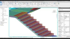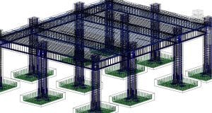
A concrete frame can look complete in a structural model, but the real challenge often begins when reinforcement needs to be modeled bar by bar. For engineering and construction projects across New York, Rebar Detailing in Revit helps teams convert design intent into precise reinforcement layouts that support fabrication, quantity takeoff, and construction coordination.
For BIM service providers such as Strand-Co, rebar detailing is more than placing bars in concrete., rebar detailing is more than placing bars in concrete. It involves interpreting structural drawings, modeling reinforcement accurately, checking for clashes, and generating schedules that fabricators, contractors, and site teams can rely on.
Why rebar detailing matters in structural BIM
Reinforced concrete structures depend on properly placed steel bars for strength and durability. If reinforcement is modeled incorrectly, the problem may not appear until fabrication or construction begins. That can lead to rework, delays, and material waste.
Rebar detailing within a BIM environment improves coordination by making reinforcement visible in the 3D model. Engineers, detailers, contractors, and fabricators can review the same information before work reaches the site. This reduces misunderstandings and helps ensure that bars fit within the concrete elements as designed.
A well-developed rebar model also supports quantity takeoffs and cost estimation. Because each bar is modeled with its size, spacing, and length, schedules can be generated directly from the model instead of being calculated manually.
Preparing the Revit model before detailing
Before reinforcement is added, the structural model should be clean, coordinated, and complete. The quality of the host model has a direct effect on the quality of the rebar detail.
Check structural elements and levels
Start by checking that beams, columns, slabs, walls, and foundations are modeled correctly. Make sure their dimensions, levels, and offsets match the approved drawings. Small mistakes in their shapes can cause problems when adding bars. Check beams, columns, slabs, walls, and foundations carefully to avoid issues. Verify that everything matches the drawings.
Verify cover settings and material properties
Concrete cover settings are really important. They decide how far the reinforcement is from the surface. In Revit, you can set cover values for sides of structural elements. You should check these values before putting in any rebar. They help you place rebar correctly. Also, incorrect settings can cause problems.
Material properties and structural families should also be checked. Using the correct concrete and reinforcement settings helps maintain consistency across the project.
Coordinate with structural drawings
When we do rebar detailing, we should always look at the approved structural drawings and design calculations for the building. Detailers need to know about the rebar diameters, the space between the rebars, and how long the laps, hooks, and bends are in the rebar. They also need to know about the reinforcement zones before they start making the model of the rebar.
Core workflow for Rebar Detailing in Revit
The workflow for rebar detailing follows a logical sequence. Each step builds on the previous one and contributes to a reliable reinforcement model.
Create rebar settings and bar types
Set up the required rebar shapes and bar diameters and hooks and bend radii at the start of the project. Using rebar types is a good idea because it helps keep things consistent and makes the schedules a lot easier to manage. This way you can focus on the shapes and bar diameters and hooks and bend radii throughout the project.
Select the host structural element
In Revit, reinforcement is placed inside a beam, a column, a slab, or a footing. Select the correct host to put the reinforcement in so the bar is connected to the concrete and it will update correctly if you change the shape of the thing.
Place primary reinforcement
Primary reinforcement carries the main structural forces. For a beam, this may include bottom longitudinal bars and top bars near supports. For a slab, it may include main reinforcement in one direction.
Add secondary reinforcement and stirrups
Secondary reinforcement gives help and keeps cracks under control. In beams and columns, extra metal, like stirrups or ties, is added to resist against shear forces. They also keep the bars in place.
Adjust spacing, layout, and constraints
When the bars are put in place, the spacing and layout rules are changed to fit the drawings. The Revit program lets users decide on the spacing of the bars. They can choose to have a fixed space between the bars and can set a maximum space. Constraints help keep reinforcement aligned with the host element.
Review reinforcement in 3D views
3D views are essential for checking the placement of reinforcement. The models let detailers see congestion, where things are not covered enough or where bars are getting in the way of embedded items. Looking at the model in 3D really helps fix problems before the drawings are sent out.
Generate schedules and shop drawings
Once the reinforcement is modeled and checked, Revit can create bar bending schedules, quantity takeoffs, and detailed reinforcement drawings. These outputs give fabricators and site teams the information they need to cut, bend, and place the reinforcement.
Modeling reinforcement in common structural elements
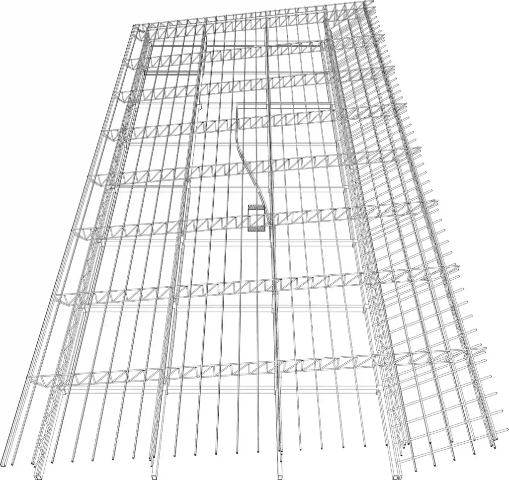
Different structural elements require different detailing approaches. Understanding the reinforcement behavior of each element helps produce accurate models.
Beams
Beam reinforcement typically includes bottom bars, top bars over supports, stirrups, and additional bars at critical sections. Careful attention should be given to anchorage lengths and the arrangement of bars near beam-column joints.
Columns
Column reinforcement usually consists of vertical bars and lateral ties. The spacing of ties may vary near the top and bottom of the column, where confinement requirements are often higher.
Slabs
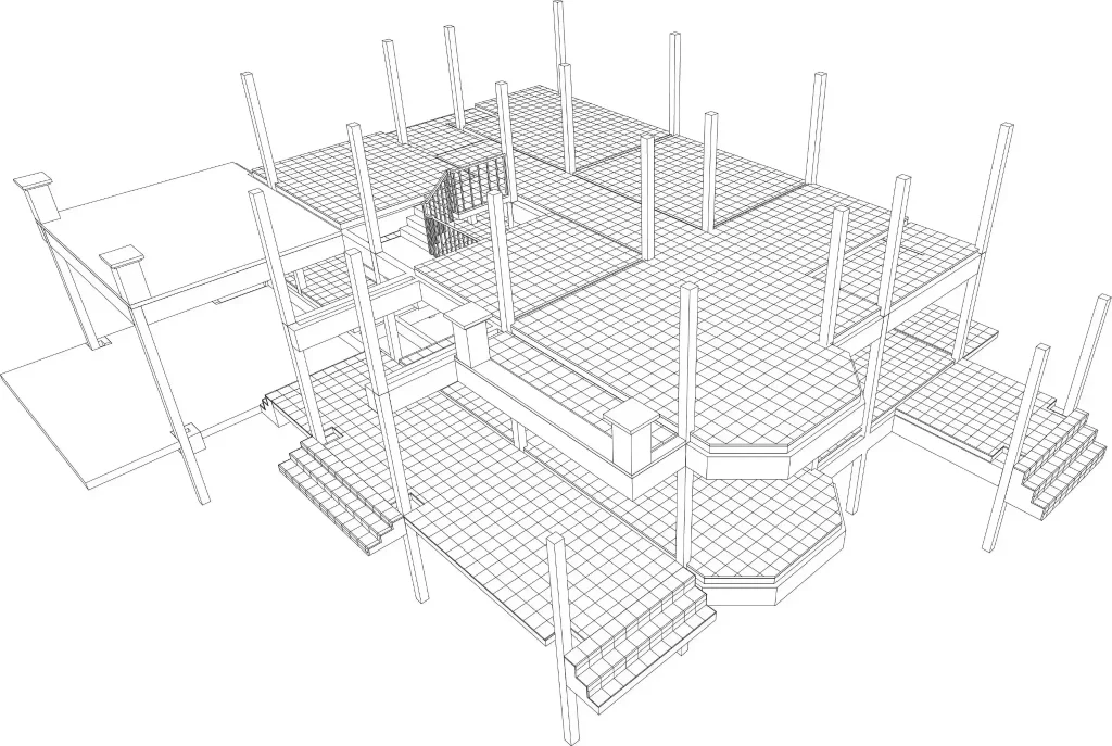
Slab reinforcement has bars, distribution bars, and extra reinforcement around openings or where loads are concentrated. For slabs, the reinforcement is usually shown as groups of bars spaced out in each direction.
Foundations
Footings and foundations require reinforcement that supports load transfer to the soil. Detailing should consider bottom reinforcement, top reinforcement where required, and bar extensions into connected structural elements.
A practical project scenario
On a mid-rise residential project, a structural BIM team was tasked with detailing reinforcement for approximately 200 reinforced concrete elements, including beams, columns, slabs, and footings. The initial design drawings were complete, but several beam-column junctions contained dense reinforcement.
During the Revit detailing process, the team used 3D views to review these congested areas. They identified overlapping stirrups and insufficient spacing between longitudinal bars. After coordinating with the structural engineer, the reinforcement arrangement was adjusted while maintaining the required design capacity.
The revised model was then used to generate bar schedules and shop drawings. According to the project team, resolving these issues in the BIM model reduced the need for field adjustments and helped keep reinforcement fabrication on schedule.
Tools and features that support efficient detailing
Revit provides several tools that make reinforcement modeling more efficient and reliable.
- Rebar tool: Places individual bars within host elements.
- Rebar sets: Creates multiple bars with consistent spacing.
- Area reinforcement: Models reinforcement over larger slab or wall areas.
- Path reinforcement: Places bars along a defined path.
- Bar bending schedules: Extracts quantities, lengths, and shapes directly from the model.
- 3D visualization: Helps review reinforcement placement and identify clashes.
Using these features effectively can save time and improve the accuracy of reinforcement documentation.
Common challenges in Revit rebar detailing
Even with advanced tools, rebar detailing can present several challenges. Recognizing these issues early helps teams avoid delays.
Reinforcement congestion
Congestion happens a lot at beam-column joints. It also occurs at foundation intersections and areas with lots of reinforcement. When many bars are packed into a small space, it can make construction really tough. That’s why it’s crucial to review these areas in 3D.
Changing design revisions
Structural designs can change during working on a project. Detailers need to make changes to the reinforcement that’s easy and fast. They should be able to update the reinforcement without having to redo a lot of the model.
Coordination with other disciplines
Mechanical, electrical, and plumbing components often go through the structure of a building. Make sure that these things work well together in the BIM model. This helps to ensure that the strong parts of the building do not get in the way of sleeves, ducts, pipes, and other things that are stuck in the building.
Maintaining schedule accuracy
Schedules are only accurate if the model is good. Even if the right information about bar parameters, lengths, or quantities is entered, it will probably have mistakes in it. Always double-check everything to make sure it is correct before you finish your documents.
Best practices for accurate structural BIM modeling
Experienced detailers follow several practices to improve the reliability of reinforcement models.
- Use standardized rebar families and naming conventions.
- Apply correct concrete cover settings before placing bars.
- Model reinforcement according to approved structural drawings and codes.
- Review congested areas in 3D views before issuing drawings.
- Coordinate with structural engineers when detailing conflicts arise.
- Validate bar schedules against the model before fabrication.
When people do rebar detailing, one thing that gets them into trouble is that they only look at plan views. The reinforcement looks fine in 2D. When you look at it in 3D, you might see problems, like overlapping or not being spaced out enough.
Benefits of a BIM-based rebar workflow
Using Revit for reinforcement modeling offers several practical advantages for structural projects.
Better coordination
Because reinforcement is modeled within the structural BIM model, it can be coordinated with other disciplines. This reduces the likelihood of conflicts during construction.
Improved visualization
3D reinforcement models help engineers, contractors, and fabricators understand the arrangement of bars more clearly than traditional 2D drawings alone.
Accurate quantity takeoffs
Bar schedules generated from the model provide reliable quantities for estimation and procurement. This helps control material usage and reduce waste.
Faster revision management
When structural elements change, associated reinforcement can often be updated within the model. This is more efficient than revising drawings manually.
Higher construction reliability
Detailed BIM models provide clearer guidance for fabrication and site installation. This can reduce errors, rework, and delays during construction.
How Strand-Co supports structural BIM and rebar detailing
For firms seeking reliable structural BIM support, Strand-Co provides services related to structural BIM modeling, Revit modeling, and rebar detailing workflows. These services help project teams create coordinated reinforcement models that support design review, quantity takeoff, fabrication, and construction planning.
A structured BIM workflow also improves communication between engineers, detailers, contractors, and fabricators. By working from a coordinated model, teams can identify issues earlier and maintain better control over project documentation.
Closing thoughts
Rebar detailing in Revit plays a critical role in structural BIM modeling because it connects design intent with construction-ready reinforcement information. A clear workflow helps teams prepare the model, place reinforcement accurately, review conflicts, and generate reliable schedules and drawings.
Need expert support? Contact Strand-Co to discuss your next structural BIM project.
Projects that invest in accurate reinforcement modeling often experience smoother coordination and fewer site adjustments. As BIM continues to shape the construction industry, a disciplined rebar detailing workflow will remain essential for delivering efficient, high-quality structural projects.
FAQ’s
What is rebar detailing in Revit?
Rebar detailing in Revit is the process of modeling reinforcing steel within concrete structures using BIM software. It allows engineers and detailers to create accurate reinforcement layouts, generate bar schedules, and produce construction-ready drawings.
Why is Revit preferred for structural rebar detailing?
Revit provides intelligent 3D modeling, automatic schedule generation, and better coordination between structural, architectural, and MEP disciplines. It also helps identify clashes early, reducing errors during fabrication and construction.
Can Revit generate rebar schedules automatically?
Yes. Once reinforcement is modeled correctly, Revit can automatically generate bar bending schedules, quantity takeoffs, and reinforcement drawings. These schedules update as the model changes, improving accuracy and saving time.
How does BIM improve the rebar detailing process?
BIM improves rebar detailing by creating a coordinated 3D model where reinforcement can be reviewed alongside other building systems. This helps detect conflicts, improves communication among project teams, and reduces costly rework during construction.
What information is needed before starting rebar detailing in Revit?
Before beginning rebar detailing, you’ll typically need approved structural drawings, reinforcement specifications, concrete cover requirements, bar sizes, design codes, and the completed structural BIM model. Having accurate project information ensures the reinforcement model is both precise and construction-ready.