Key Takeaways
- Rebar placement tolerances define acceptable variation from the specified reinforcement location.
- ACI 117 is a key reference for concrete construction tolerances in the United States.
- ACI 117-10 provides reinforcement location tolerances based on member thickness or depth.
- Placement tolerance should not be confused with concrete cover requirements.
- Reinforcement spacing, bar ends, bends, laps, and development regions also require careful control.
- Project specifications can establish requirements that differ from general ACI tolerances.
- Tolerance stacking can create problems when reinforcement interacts with formwork, embeds, openings, MEP systems, and other components.
- Accurate rebar detailing and shop drawings reduce field interpretation and coordination problems.
- 3D rebar modeling can help identify congestion and constructability issues before construction.
- Pre-pour inspection provides an important opportunity to identify and correct reinforcement deviations.
Reinforcing steel must be positioned accurately enough to satisfy structural, durability, and constructability requirements. At the same time, concrete construction cannot realistically be performed with zero dimensional variation. This is why rebar placement tolerances establish an acceptable range around the specified position of reinforcing steel.
For engineers, contractors, detailers, fabricators, and inspectors, understanding these tolerances is important because even relatively small deviations can affect concrete cover, reinforcement spacing, effective depth, development length, and coordination with openings or embedded items. The goal is not simply to place every bar at an exact theoretical coordinate. The goal is to keep reinforcement within the limits established by the applicable standards and project documents.
In the United States, ACI 117 is a key reference for concrete construction tolerances. The current ACI publication page identifies ACI 117-10 as the specification for tolerances for concrete construction and materials, reapproved in 2015. Its reinforcement section addresses reinforcement fabrication and assembly, reinforcement location, and related requirements.
What Are Rebar Placement Tolerances?
Rebar placement tolerances define the amount of permitted variation between the specified location of reinforcing steel and its actual location in the completed concrete member. Structural drawings establish the intended position of bars, but field conditions can introduce small deviations during fabrication, installation, tying, formwork, concrete placement, and construction activities.
A tolerance provides a practical boundary for those variations. It does not mean that reinforcing steel can be deliberately placed anywhere within the tolerance range. The reinforcement should still be installed as accurately as reasonably possible and in accordance with the approved drawings, specifications, and applicable standards.
Placement tolerances can affect several aspects of reinforcement installation, including the location of bars, concrete cover, spacing, bar ends, bends, laps, development regions, and reinforcement elevation. These requirements become especially important when reinforcement interacts with other components such as embeds, sleeves, openings, mechanical systems, architectural elements, and formwork.
Why Rebar Placement Accuracy Matters
The location of reinforcing steel directly influences the structural behavior of reinforced concrete. For example, moving flexural reinforcement away from its intended position can change the effective depth of a beam or slab. That change can affect the assumptions used in structural design and may become significant when deviations are large or occur in critical regions.
Concrete cover is another major consideration. Reinforcement must remain sufficiently far from the concrete surface to satisfy the applicable durability and protection requirements. At the same time, excessive movement in the opposite direction can alter the intended structural position of the bar. This is why reinforcement location and concrete cover need to be evaluated together.
Placement accuracy also affects constructability. Crowded reinforcement can restrict concrete flow and make consolidation difficult. Poorly positioned bars can interfere with embeds, sleeves, couplers, openings, or other trades. ACI has specifically recognized that reinforcement, formwork, layout, and other construction tolerances can interact and create compatibility problems even when individual tolerances appear acceptable.
What Standards Govern Rebar Placement Tolerances?
Rebar placement requirements are normally established through a combination of structural codes, specifications, project drawings, and referenced industry standards. No single tolerance value should automatically be applied to every project because the contract documents can establish project-specific requirements.
ACI 117
ACI 117, Specification for Tolerances for Concrete Construction and Materials, is one of the principal references for reinforcement placement tolerances in U.S. concrete construction. ACI’s published ACI 117-10 document includes a dedicated section covering reinforcement location.
ACI 117 is intended to provide standard tolerances that specification writers and ACI committees can use when establishing concrete construction requirements. The standard should be read together with the project’s structural drawings and specifications rather than treated as a replacement for project-specific requirements.
ACI 318
ACI 318 provides requirements for structural concrete design and construction. It should not be confused with ACI 117’s construction tolerance provisions. Designers and contractors need to consider the relationship between structural requirements and permissible field variation when evaluating reinforcement placement.
The distinction matters because a construction tolerance is not simply a design allowance. The fact that a bar may be within a specified placement tolerance does not mean that every resulting condition is automatically acceptable. Cover, development, spacing, structural geometry, and project requirements still need to be satisfied.
ACI 301 and Project Specifications
ACI 301 can also form part of the construction specification framework for structural concrete. More importantly, project specifications can establish requirements that are different from general tolerance provisions when the project requires greater accuracy.
ACI’s tolerance guidance emphasizes coordination between concrete construction and interfacing systems. It also recognizes that more restrictive tolerances may be required for particular applications.
CRSI Guidance
The Concrete Reinforcing Steel Institute also provides industry guidance related to reinforcing steel detailing, fabrication, and placement. CRSI resources are useful when developing practical reinforcement details and coordinating reinforcing steel with construction conditions.
For this reason, a complete tolerance review should consider the applicable ACI requirements, CRSI guidance where relevant, structural drawings, specifications, and the actual conditions of the project.
ACI 117 Rebar Placement Tolerances
ACI 117-10 provides specific tolerances for the location of nonprestressed reinforcement. The tolerance varies according to the thickness or depth of the concrete member. The commonly referenced values are:
| Member thickness or depth | Reinforcement placement tolerance |
|---|---|
| 4 in. or less | ±1/4 in. |
| Over 4 in. to 12 in. | ±3/8 in. |
| Over 12 in. | ±1/2 in. |
These values should be treated as reference requirements from ACI 117-10 rather than a universal permission to shift reinforcement by the maximum amount. The applicable project documents may establish different requirements, and other provisions can affect whether a particular bar location is acceptable.
ACI’s supporting material also illustrates that reinforcement position, reinforcement cover, and reinforcement spacing are separate considerations. For example, an ACI presentation based on ACI 117-10 shows reinforcement position tolerance separately from cover and spacing requirements.
Rebar Cover Tolerances

Concrete cover is one of the most important factors when evaluating reinforcement placement. Cover provides the required separation between reinforcement and the concrete surface and contributes to the durability and protection of reinforcing steel.
A reinforcement inspection should therefore determine both the actual bar position and the resulting cover. A bar may appear correctly aligned relative to neighboring bars while still producing inadequate cover at the formwork surface. Conversely, increasing cover excessively can move reinforcement away from its intended structural location.
ACI’s supporting guidance notes that cover tolerance can become particularly important in environments involving chloride exposure and cautions that the magnitude of a permitted reduction in cover may need to be restricted for specific conditions.
Rebar Spacing Tolerances
Reinforcement spacing is another important part of placement control. Drawings may identify reinforcement by a specific spacing, bar count, or arrangement. Maintaining that configuration helps ensure that reinforcement is distributed as intended by the structural design.
Spacing also has a practical effect on concrete placement. When bars are placed too closely together, concrete may have difficulty passing through the reinforcement and achieving adequate consolidation. When spacing is changed without engineering review, the reinforcement distribution may also differ from the approved design.
For that reason, a general reinforcement location tolerance should not be interpreted as permission to arbitrarily change the spacing shown on structural drawings. The specified reinforcement arrangement remains the primary installation reference.
Tolerances for Bar Ends, Bends, and Embedded Length
Reinforcement tolerances are not limited to the centerline location of a bar. The position of bends and bar ends can also be important, particularly around supports, joints, openings, walls, columns, and anchorage regions.
A bar that appears correctly positioned in plan can still create a problem if its termination point does not provide the required development or anchorage. Similar concerns apply to lap splices, hooks, dowels, and reinforcement that extends into adjoining structural members.
ACI 117 includes provisions covering reinforcement fabrication and assembly as well as reinforcement location. This distinction is important because reinforcement fabrication accuracy and field placement accuracy are related but separate quality-control considerations.
Rebar Placement Tolerances by Structural Element
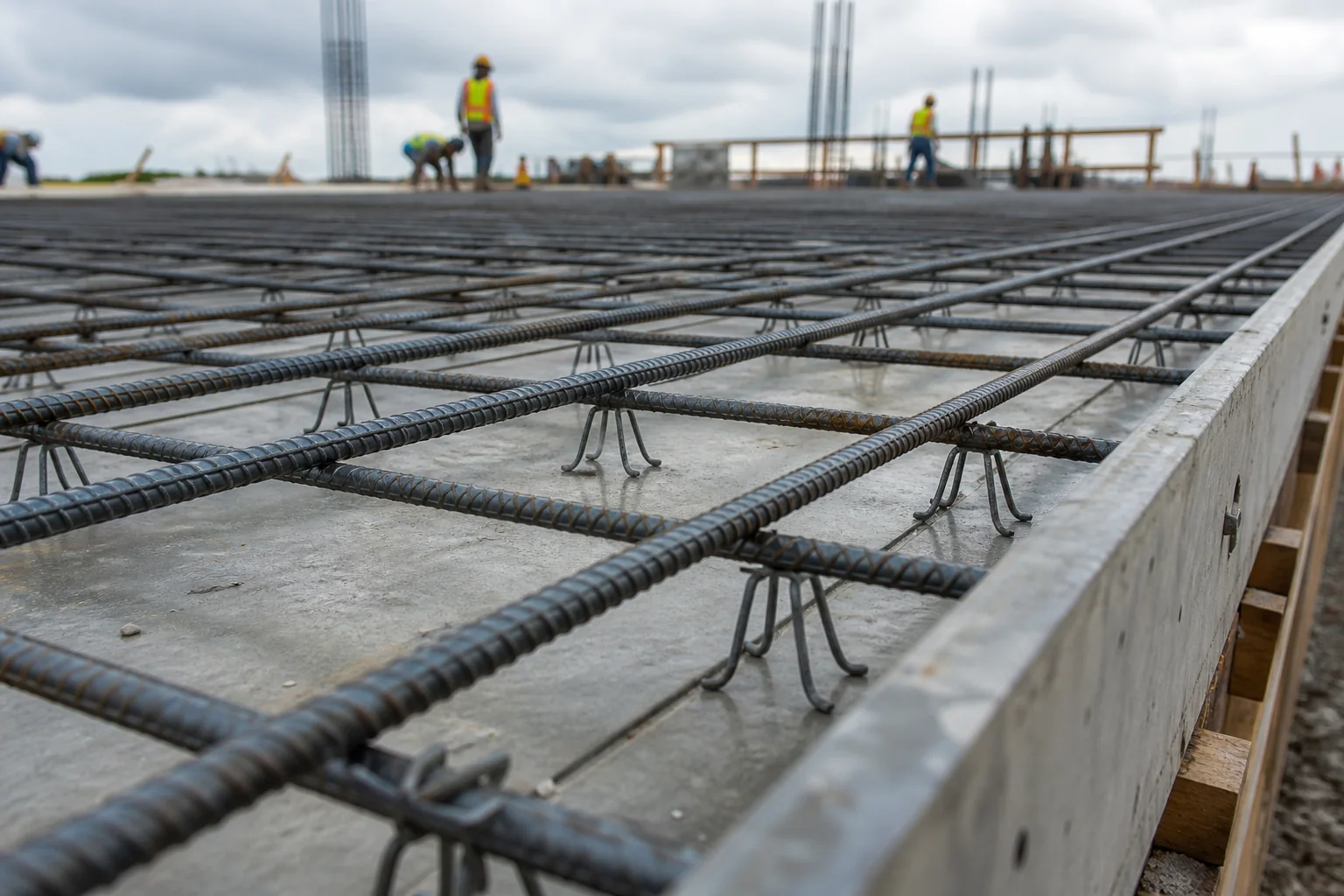
Rebar placement tolerances for slabs, beams, columns, walls, and foundations, with key accuracy and installation considerations.
Slabs
Slabs can contain multiple layers of reinforcement, temperature and shrinkage reinforcement, support bars, opening reinforcement, and additional steel around columns or walls. Maintaining the designed elevation can therefore be challenging.
Reinforcement supports such as chairs and bolsters help keep bars at the required elevation during construction. Field crews also need to consider construction traffic and concrete placement because workers, equipment, hoses, and other activities can displace reinforcement before or during the pour.
Beams
Beam reinforcement commonly includes longitudinal bars, stirrups, top reinforcement, bottom reinforcement, side bars, and additional steel around supports. Congestion becomes particularly significant near beam-column joints.
Accurate detailing allows contractors to identify congested areas before installation. Sections and enlarged details can provide additional information where a standard plan view does not adequately communicate the reinforcement arrangement.
Columns
Column reinforcement requires control of longitudinal bar locations, ties or hoops, cover, lap regions, and alignment. A reinforcement cage can shift during handling, installation, or concrete placement if it is not adequately supported.
Pre-pour inspection is therefore important for confirming that the installed cage remains consistent with the approved structural drawings.
Walls
Reinforced concrete walls can contain one or two reinforcement curtains along with boundary reinforcement, openings, embeds, and concentrated reinforcement around structural connections. Double-curtain walls require careful control of the spacing and location of each layer.
Because several systems may need to occupy the same wall zone, coordinated detailing can reduce field conflicts and help crews understand the intended reinforcement arrangement before construction.
Foundations
Footings, mats, pile caps, and other foundation elements can contain large quantities of reinforcing steel. Bottom cover and reinforcement elevation are particularly important because the steel must remain supported above the formwork or prepared surface.
Heavy reinforcement can also make field movement difficult. Proper support systems and clear reinforcement drawings are therefore important for maintaining the intended arrangement.
Common Causes of Rebar Placement Errors
Even a well-detailed reinforcement package can encounter field deviations. Common causes include:
Inaccurate Formwork
If the formwork dimensions or location differ from the approved drawings, reinforcement positioning can be affected.
Insufficient Bar Supports
Missing or poorly spaced chairs, bolsters, spacers, or supports allow reinforcement to move during installation and concrete placement.
Heavy Construction Traffic
Workers, equipment, hoses, and concrete operations can displace reinforcement, especially in slabs and large mats.
Congested Reinforcement
When several layers of reinforcement occupy a small space, maintaining the designed spacing and cover becomes more difficult.
Poor Coordination
Unresolved conflicts between reinforcement, embeds, sleeves, MEP systems, openings, and structural components can force field crews to move bars.
Incomplete Drawings
Ambiguous dimensions, missing sections, unclear bar marks, or inconsistent schedules can increase the likelihood of field interpretation errors.
Last-Minute Changes
Design revisions that are not incorporated into the latest shop drawings can result in crews installing outdated reinforcement layouts.
How Rebar Detailing Helps Control Placement Tolerances
Accurate rebar detailing provides the construction team with a clear representation of the intended reinforcement arrangement. A good detailing package communicates bar sizes, marks, spacing, locations, bends, laps, cover, sections, elevations, and other information required for fabrication and installation.
This reduces the amount of interpretation required in the field. It also allows potential problems to be identified before reinforcement is fabricated. Strand-Co’s rebar detailing services emphasize detailed reinforcement drawings, bar positioning, splicing requirements, clear spacing, and construction information.
The benefit becomes even greater on complicated structures. High-rise buildings, transfer structures, foundations, bridges, shear walls, and heavily reinforced connections can contain thousands of individual bars. Detailed drawings help translate the structural engineer’s design intent into an installation-ready reinforcement package.
How 3D Rebar Modeling Improves Placement Accuracy
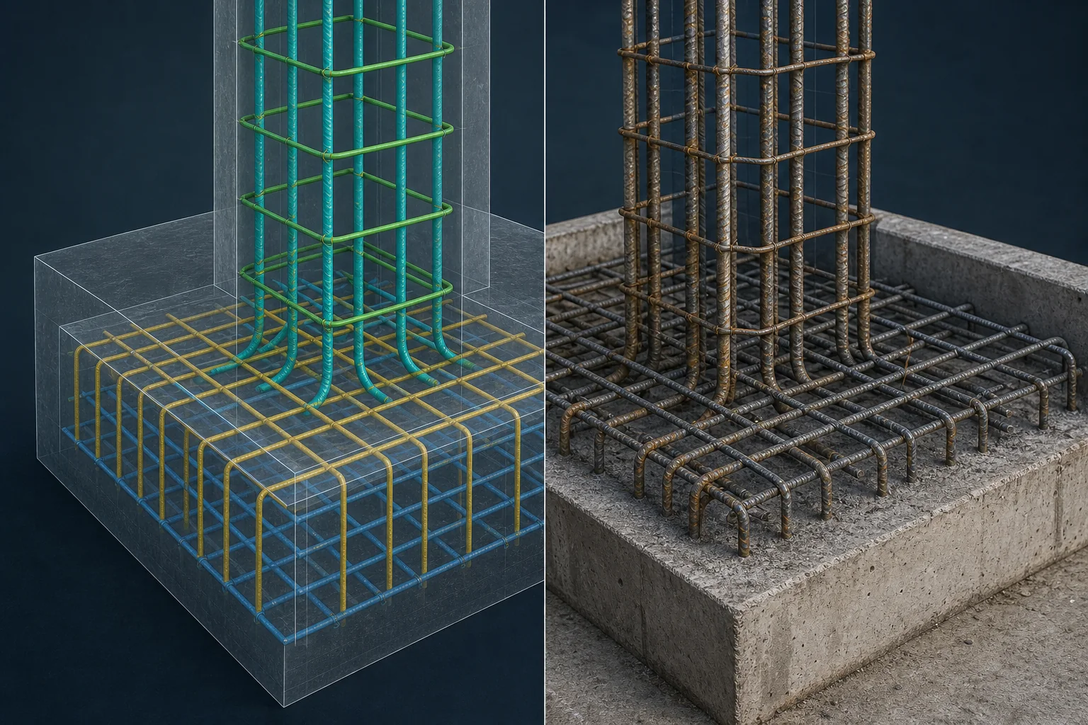
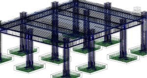
Three-dimensional rebar modeling adds another level of coordination by allowing project teams to visualize reinforcement as a complete assembly rather than as isolated lines on a two-dimensional drawing.
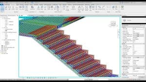
A 3D model can help identify congested reinforcement, insufficient clearances, conflicts with embeds, openings, and MEP systems, and difficult-to-construct bar arrangements. It can also help detailers review concrete cover and reinforcement relationships before drawings are issued.
For complex projects, this early coordination can reduce the number of problems discovered after fabrication or at the jobsite. Strand-Co’s BIM and Revit workflows incorporate 3D reinforcement modeling and coordination to help review reinforcement geometry and constructability before construction.
Rebar Placement Tolerances and BIM Clash Detection
BIM clash detection is useful for reinforcement coordination, but tolerance management goes beyond identifying physical clashes. A bar does not necessarily have to intersect another component to create a constructability problem.
For example, reinforcement may technically fit inside a wall while leaving insufficient room for concrete consolidation. Similarly, a bar may avoid an opening but be positioned too close to an embed or another reinforcement layer to allow practical installation.
ACI’s guide on tolerance compatibility specifically addresses the interaction between concrete construction and systems such as embedded items, openings, couplers, and other components. The guide emphasizes coordination because incompatible tolerances can affect construction quality, cost, and schedule.
Best Practices for Maintaining Rebar Placement Tolerances
The most effective approach is to control reinforcement placement throughout the project rather than waiting until the pre-pour inspection.
Start by confirming that the detailer and construction team are working from the latest approved structural drawings and specifications. Concrete cover, reinforcement spacing, bar elevations, lap locations, development regions, openings, and embeds should be coordinated before fabrication begins.
During installation, reinforcement should be properly supported and tied so that it remains in position during construction. Congested areas should receive additional attention because they are more likely to experience field adjustments. Where a conflict exists, the preferred solution is to resolve it through the established engineering and coordination process rather than moving critical reinforcement without approval.
Finally, inspect the reinforcement before concrete placement. The inspection should verify the installed reinforcement against the approved drawings and project requirements, with particular attention to cover, spacing, elevations, laps, dowels, supports, openings, and congested areas.
What Happens When Rebar Is Outside the Allowed Tolerance?
A reinforcement deviation does not automatically mean that a concrete member has failed or must be demolished. The actual condition should first be measured and compared against the applicable project requirements.
The project team may need to evaluate the actual bar location, cover, effective depth, development and anchorage, splice conditions, structural design assumptions, and other relevant requirements. The responsible structural engineer or designated authority should determine whether the condition can be accepted or requires correction.
Field crews should not independently cut, remove, relocate, or reduce critical reinforcement simply because the installed arrangement differs from the drawings. Any significant deviation should be documented and addressed through the project’s approved engineering and quality-control procedures.
Tolerance Stacking: Why Small Errors Can Become Big Problems
Tolerance stacking occurs when several individual variations combine to create a larger overall deviation. This can happen when reinforcement interacts with formwork, embeds, openings, architectural finishes, MEP systems, couplers, or other construction components.
For example, each component may individually remain within its permitted tolerance, but the combined variation may reduce the available space around an opening or embedded item. This can produce a problem even though no single component appears significantly out of position.
ACI’s tolerance compatibility guidance specifically addresses this issue and recommends coordination among the various systems that interface with concrete. Early tolerance coordination can reduce field conflicts, rework, schedule delays, and construction uncertainty.
Rebar Placement Tolerance vs. Rebar Fabrication Tolerance
Rebar fabrication tolerance and placement tolerance describe two different stages of reinforcement work.
Fabrication tolerance concerns the dimensional accuracy of a reinforcing bar after it has been cut and bent. Placement tolerance concerns the location of that fabricated bar after it is installed in the structure.
A reinforcing bar can therefore be fabricated correctly but installed incorrectly. The opposite can also occur. Quality control needs to address both processes because accurate fabrication alone cannot guarantee accurate field placement.
Clear bar schedules, bending information, shop drawings, and coordinated reinforcement models can help reduce fabrication errors, while proper supports, installation procedures, field measurements, and pre-pour inspections help control placement.
Rebar Placement Tolerances and Shop Drawings
Rebar shop drawings serve as an important link between structural design and field installation. They translate design requirements into information that fabricators and installers can use to produce and position reinforcement.
A well-developed package should make bar marks, sizes, shapes, spacing, locations, laps, bends, cover, sections, and reinforcement transitions clear. Complex areas may require enlarged details so that installers can understand how several reinforcement layers interact.
This is particularly valuable when the structure contains congestion or unusual geometry. Strand-Co’s rebar shop drawing approach focuses on clear reinforcement information, bar positioning, splicing, dimensions, and site coordination.
Rebar Placement Tolerance Inspection
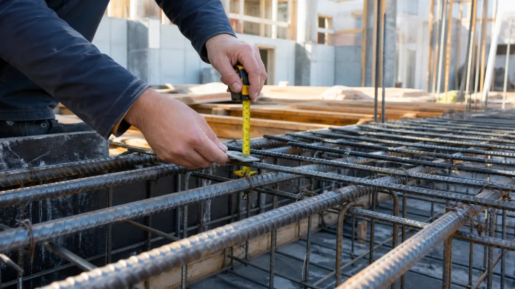
Before concrete is placed, the reinforcement should be inspected against the latest approved drawings and specifications. The inspection should confirm that the bars are correctly sized, spaced, supported, and positioned and that the required cover is maintained.
Particular attention should be given to beam-column joints, wall boundaries, openings, laps, couplers, dowels, foundation reinforcement, and other congested areas. These locations are more likely to experience deviations or field modifications.
If a significant discrepancy is identified, it should be documented and referred to the appropriate project authority. Early identification is important because correcting reinforcement before concrete placement is generally much easier than addressing a problem after the concrete has hardened.
Conclusion
The placement tolerances for rebar establish practical limits for the safe and consistent construction of reinforced concrete. By acknowledging inevitable field variances, they also set outer boundaries for protecting structural integrity, concrete cover, constructability, and overall coordination.
Achieving successful tolerance control starts even before reinforcement is placed on the jobsite. Proper construction drawings, rebar detailing, shop drawings, 3D modeling, correct reinforcement supports, field inspection, and engineering decisions are all important for the sound outcome of concrete construction. the ACI guidelines emphasize the importance of considering tolerances in relation to the interaction between reinforcement, formwork, embedded items, openings, and other items.
For highly complex concrete structures, professional rebar detailing and BIM coordination can make all the difference. By addressing reinforcement conflicts and constructability concerns before fabrication and installation, projects can minimize rework, improve communication, and empower the field with a clear vision of the reinforcement needed to achieve the desired concrete structure. Strand-Co’s rebar detailing, shop drawing, and BIM services connect design intent with field-ready details and coordinated reinforcement information.
Frequently Asked Questions
What is the standard tolerance for rebar placement?
ACI 117-10 provides reinforcement location tolerances based on member thickness or depth. For nonprestressed reinforcement, commonly referenced values are ±1/4 inch for members up to 4 inches thick, ±3/8 inch for members over 4 through 12 inches, and ±1/2 inch for members over 12 inches. Project specifications can establish different requirements, so the contract documents should always be checked.
Is rebar placement tolerance the same as concrete cover tolerance?
No. They are related but separate requirements. Placement tolerance concerns the permitted variation in reinforcement location, while concrete cover requirements establish the required distance between reinforcement and the concrete surface.
What happens if rebar is out of tolerance?
The actual condition should be measured and evaluated against the applicable drawings, specifications, structural requirements, and standards. If the deviation could affect structural performance or another project requirement, the responsible engineer should determine the appropriate corrective action.
Does ACI 318 specify rebar placement tolerances?
ACI 318 provides structural concrete design and construction requirements, while ACI 117 is the primary ACI reference for concrete construction tolerances. They should be considered together with project-specific specifications.
Why is concrete cover important when checking rebar placement?
Concrete cover helps protect reinforcing steel and contributes to durability and other performance requirements. Incorrect bar positioning can reduce cover or move reinforcement away from its intended structural position.
Can BIM help maintain rebar placement tolerances?
Yes. A coordinated 3D rebar model can help teams review reinforcement geometry, cover, congestion, openings, embeds, and other potential conflicts before fabrication and installation.
Can project specifications require stricter tolerances?
Yes. Project documents can establish more restrictive requirements where greater accuracy is necessary. ACI’s tolerance compatibility guidance specifically discusses the need to coordinate tolerances and accommodate project-specific conditions.