
A structured steel detailing QA/QC checklist helps ensure that structural steel models, shop drawings, erection drawings, and material reports are accurate before they reach the fabrication shop. Even a minor detailing mistake can cause material waste, production delays, field modifications, or installation problems.
Quality assurance establishes the standards and procedures that guide the detailing process. Quality control focuses on checking the model, drawings, connections, dimensions, and deliverables against those standards. Applying both processes throughout the project helps produce coordinated and fabrication-ready steel drawings.
Why Is QA/QC Important in Steel Detailing?
Structural steel detailing converts engineering drawings into precise information that fabricators and erectors can use. Every beam, column, plate, bolt, and weld must be correctly represented in the model and associated drawings.
A reliable QA/QC process helps identify missing information, design conflicts, modeling mistakes, and drawing inconsistencies before fabrication begins. It also reduces RFIs, repeated revisions, material waste, shop interruptions, and costly corrections at the construction site.
Quality checks should not be treated as a final task completed immediately before submission. They should be included at every stage, from reviewing the contract documents to releasing approved drawings for fabrication.
Difference Between Quality Assurance and Quality Control
Quality assurance, or QA, is a preventive process. It establishes the procedures, responsibilities, standards, templates, and review stages that the detailing team must follow.
Quality control, or QC, is an inspection process. It checks the actual steel model, drawings, reports, and files to identify errors and confirm that the required standards have been followed.
A complete steel detailing system needs both. QA builds a consistent workflow, while QC verifies that each project deliverable is accurate and complete.
Review Project Inputs Before Detailing
The QA/QC process should begin before the structural model is created. The detailer must confirm that all necessary project information is available and that the latest document revisions are being used.
Review the following project inputs:
- Structural design drawings
- Architectural drawings
- Project specifications
- Connection design criteria
- Design calculations
- Applicable codes and standards
- Fabricator preferences
- Erection requirements
- Addenda and approved RFIs
- Material and coating specifications
- Project schedules and release sequences
Any missing, unclear, or conflicting information should be documented and submitted through an RFI. Unverified assumptions can create errors that spread across the model, shop drawings, and fabrication data.
Confirm the Project Setup
A consistent project setup supports accurate modeling and drawing production. Before detailing begins, the team should verify the drawing units, grid system, floor levels, model coordinates, orientation, reference points, and member-numbering rules. These details must match the structural and architectural drawings.
The review should also confirm drawing templates, title blocks, fabricator standards, file-naming conventions, assembly-numbering rules, output formats, and revision procedures. Identifying setup errors early prevents them from affecting the entire structural model and drawing package.
Structural Steel Model QA/QC Checklist
The structural model should be checked for accuracy, completeness, coordination, and constructability. Automated clash detection can help identify conflicts, but it should not replace a professional manual review.
Member Sizes and Locations
Confirm that all beams, columns, braces, joists, trusses, and miscellaneous steel members match the structural drawings. Check member sizes, lengths, profiles, slopes, rotations, offsets, and elevations.
Members should be located correctly in relation to grid lines, finished floor levels, roof slopes, walls, equipment, and other structural components.
Material Grades
Verify that every member, plate, bolt, and connection component uses the specified material grade. Incorrect material information can affect purchasing, connection performance, welding requirements, and fabrication costs.
Material grades should remain consistent between the model, drawings, bills of materials, and CNC files.
Geometry and Alignment
Check the alignment of beams, columns, braces, plates, and connection components. Confirm working points, member setbacks, framing offsets, slopes, cambers, and end elevations.
Special attention should be given to skewed connections, sloped framing, curved steel, transfer members, and complex geometry.
Clash Detection
Run clash checks between structural steel members and other building systems. Review conflicts involving concrete, mechanical ducts, pipes, electrical equipment, architectural features, cladding, stairs, and access areas.
Each detected clash should be reviewed individually because some software-generated clashes may be acceptable clearances or intentional overlaps.
Connection Detailing Checklist
Steel connections require careful checking because they directly affect fabrication, assembly, erection, and structural performance. The connection details must reflect the engineer’s design intent and project requirements.
Bolted Connections
Check each bolt’s diameter, grade, quantity, spacing, edge distance, and hole type. Bolt patterns must follow project requirements and provide sufficient access for installation and tightening during fabrication or field erection.
Welded Connections
Verify each weld’s type, size, length, location, and symbols while clearly distinguishing shop welds from field welds. The checker should also confirm accessibility, clearance, preparation requirements, and fabrication practicality before releasing the drawings.
Plates, Stiffeners, and Reinforcement
Check plate dimensions, thicknesses, material grades, orientations, and edge preparations. Stiffeners, continuity plates, doubler plates, base plates, splice plates, and gusset plates should be correctly positioned and fully dimensioned. The connection should provide sufficient clearance for bolts, welds, tools, coatings, and erection activities.
Connection Design Information
Where connection engineering is delegated, confirm that the required loads, reactions, design criteria, and calculations have been received and incorporated. Open connection-design questions should be resolved before the affected drawings are released for fabrication.

Shop Drawing Quality-Control Checklist
Shop drawings provide the information needed to manufacture individual steel members and assemblies. Every drawing should be clear, complete, readable, and consistent with the coordinated model.
Dimensions and Geometry
Confirm overall member lengths, hole locations, plate positions, cut dimensions, bevels, notches, slopes, and reference dimensions. Avoid duplicate or conflicting dimensions that could confuse the fabrication team. Critical dimensions should be presented clearly and measured from reliable working points.
Piece Marks and Assembly Marks
Every part and assembly should have a unique and consistent mark. Verify that piece marks shown on the drawings match the model, material lists, erection drawings, and fabrication files. Duplicated, missing, or incorrectly assigned marks can cause production and erection problems.
Bolts, Holes, and Fasteners
Check all hole sizes, bolt diameters, bolt grades, slot orientations, edge distances, and spacing. Confirm whether each connection is shop-bolted, field-bolted, or welded. Special fasteners and installation requirements should be identified clearly.
Weld Symbols and Notes
Ensure all weld symbols are complete, readable, and located correctly. Check weld sizes, lengths, pitch, preparation details, and shop or field designations. General welding notes must not conflict with project-specific details.
Material Information
Each drawing should identify the correct member sizes, plate thicknesses, material grades, quantities, and finishes. Material descriptions should match the bill of materials and project specifications.
Coatings and Surface Preparation
Confirm painting, galvanizing, fireproofing, primer, and surface-preparation requirements. Clearly identify surfaces that must remain unpainted or receive special treatment. Drain holes, vent holes, masking areas, and touch-up requirements should also be shown where applicable.
Erection Drawing QA/QC Checklist
Erection drawings guide the placement and connection of steel components at the construction site. These drawings should provide a clear overview of the structure without unnecessary fabrication detail.
The checker should verify:
- Grid lines and dimensions
- Floor and roof elevations
- Member locations and orientations
- Piece and assembly marks
- Field connections
- Bolt and weld information
- Column splice locations
- Erection sequences
- Temporary support requirements
- Match marks and reference details
- Interfaces with concrete and other trades
Base Plate and Anchor Bolt Checks
Base plates and anchor bolts connect the structural steel frame to the foundation, making dimensional accuracy essential. Even minor errors can prevent columns from fitting properly during erection and may require costly field modifications.
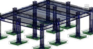
Check the base plate dimensions, thickness, hole sizes, bolt patterns, grout allowances, elevations, column orientation, and anchor bolt projections. The anchor bolt plan should also coordinate with the latest foundation and concrete drawings.
The review should confirm column grid locations, anchor bolt diameters and grades, bolt spacing, edge distances, leveling details, shear lugs, setting templates, and required field tolerances. All information must remain consistent across the model, fabrication drawings, and installation plans.
Stair, Handrail, and Miscellaneous Steel Checks
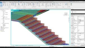
Miscellaneous steel frequently connects with concrete, walls, floors, architectural finishes, and structural framing. Check stair dimensions, riser heights, tread depths, landings, stringers, clear widths, headroom, rail heights, post spacing, and support connections for proper coordination.
Ladders, platforms, embeds, bollards, canopies, and equipment supports should also be reviewed for accurate dimensions, required clearances, material finishes, and installation details. All components must follow the contract drawings and applicable project requirements.
Bill of Materials Verification
The bill of materials must match the model and shop drawings. Verify member descriptions, plate sizes, quantities, material grades, lengths, weights, and piece marks.
The checker should look for duplicated items, missing components, incorrect quantities, and inconsistent material information. Special-order or long-lead materials should be identified early to prevent procurement delays.
CNC and Fabrication Data Checks
CNC files and machine data should only be created from the latest approved model. Before release, confirm that hole locations, cuts, notches, copes, bevels, markings, and member lengths match the approved shop drawings.
A model change may affect the CNC data even when the drawing change appears minor. For this reason, fabrication files should be regenerated and verified after relevant revisions.
Drawing-to-Model Consistency
Shop and erection drawings must remain consistent with the coordinated steel model. Manual drawing changes that are not added to the model can create conflicting information and lead to fabrication or installation errors.
The reviewer should compare critical dimensions, connections, member locations, piece marks, and material data across all deliverables. Any manual modification must be documented clearly and incorporated into the final model.
Revision Control Checklist
Revision control prevents outdated drawings and fabrication files from reaching the shop floor. Every change should be recorded, reviewed, and communicated to the appropriate project participants.
Revised deliverables should show:
- Current revision numbers
- Revision dates
- Clouded or identified changes
- Updated drawing notes
- Related RFI references
- Approval status
- Fabrication impact
- Superseded drawing records
If a change affects related assemblies, shop drawings, erection plans, reports, or CNC files, all connected deliverables must be updated.

Final Pre-Submission Review
Before submitting the steel detailing package, an independent checker should complete a thorough final review. Software warnings and automated reports can support this process, but they should not replace professional judgment and manual verification.
The checker should confirm that all review comments and RFIs have been resolved, the latest design revisions are incorporated, and the drawings match the coordinated model. Connections, dimensions, piece marks, material lists, and erection drawings must also be accurate and complete.
Finally, confirm that fabrication files were generated from the current model and that every drawing shows the correct status and revision. Only a complete, coordinated, and internally approved package should be submitted for external review.
Common Steel Detailing QA/QC Mistakes
Common quality-control failures include:
- Using outdated structural drawings
- Ignoring architectural or MEP coordination
- Releasing drawings with unresolved RFIs
- Missing member elevations or orientations
- Incorrect material grades
- Incomplete bolt and weld information
- Conflicting dimensions
- Duplicated piece marks
- Uncoordinated shop and erection drawings
- Failing to update CNC files after revisions
- Allowing fabrication from unapproved drawings
- Relying entirely on automated software checks
These mistakes are often avoidable when the detailing team follows a consistent review process.
How to Improve the Steel Detailing QA/QC Process
Clear responsibilities, consistent checks, and controlled revisions help improve drawing accuracy and reduce fabrication errors.
Assign Clear Review Responsibilities
Assign a detailer, independent checker, and final approver to each deliverable. Clear responsibilities help prevent missed checks and ensure that every drawing receives the required level of review.
Use Project-Specific Checklists
Standard templates and checklists improve consistency, but they should be adjusted for the building type, fabrication methods, connection requirements, applicable standards, and client preferences.
Maintain Strong Revision Control
Use a controlled revision register to track drawing updates, approval statuses, design changes, and superseded files. This prevents outdated drawings or fabrication data from reaching the shop floor.
Track RFIs and Coordination Issues
Maintain an updated RFI log and hold regular coordination meetings with relevant project teams. Every response and design decision should be incorporated into the model and related drawings.
Review Errors and Improve Future Work
Conduct model audits and lessons-learned reviews throughout the project. Document repeated errors, identify their causes, and update internal procedures to prevent the same problems on future projects.
Complete Steel Detailing QA/QC Checklist
Before issuing drawings for approval or fabrication, verify the following:
- Use the latest drawings, specifications, addenda, and RFIs.
- Check grids, elevations, coordinates, dimensions, and member locations.
- Confirm member sizes, material grades, plates, and reinforcement details.
- Verify all bolts, welds, holes, connections, and clearances.
- Coordinate shop drawings, erection plans, and the structural model.
- Check piece marks, material lists, coatings, CNC files, and fabrication data.
- Resolve clashes, reviewer comments, design changes, and revisions.
- Remove superseded files and complete an independent final review.
Final Thoughts
A consistent steel detailing QA/QC checklist gives project teams a reliable method for reviewing structural models, connections, shop drawings, erection plans, material reports, and fabrication files. It helps identify errors before they reach the fabrication shop or construction site.
Strand Consulting Corporation supports coordinated steel detailing and quality-control workflows that improve drawing accuracy and fabrication readiness. Careful checking, controlled revisions, and clear communication can reduce rework, protect the project schedule, and help steel components fit correctly during erection.
Frequently Asked Questions
What is a Steel Detailing QA/QC Checklist?
A Steel Detailing QA/QC Checklist is a structured review process used to verify structural steel models, connections, shop drawings, erection drawings, material reports, and fabrication files before approval or production. It helps detailers and checkers confirm that project requirements, dimensions, materials, and drawing information are accurate and coordinated.
Why is a Steel Detailing QA/QC Checklist important?
A Steel Detailing QA/QC Checklist helps identify detailing errors before they reach fabrication or the construction site. It can reduce RFIs, repeated revisions, material waste, shop interruptions, and costly field corrections while helping the detailing team maintain consistent quality throughout the project.
What should be checked in steel shop drawings?
The Steel Detailing QA/QC Checklist should include checks for member dimensions, material grades, piece marks, bolt details, weld symbols, connection information, finishes, elevations, and bills of materials. The drawings should also remain consistent with the coordinated structural model and approved project information.
Who performs quality control in steel detailing?
A qualified steel detailer or independent checker typically performs the detailed quality-control review. A project lead, senior checker, or QA/QC manager may then complete the final review. Using a consistent Steel Detailing QA/QC Checklist helps ensure that each reviewer checks the same critical project information.
How are QA and QC different in steel detailing?
Quality assurance establishes the standards, procedures, responsibilities, and review methods used to prevent errors. Quality control checks the actual structural model, shop drawings, erection drawings, connections, and fabrication files. A Steel Detailing QA/QC Checklist brings both processes together into a consistent review workflow.
When should the final QA/QC review occur?
The final QA/QC review should take place after RFIs, design revisions, coordination issues, and reviewer comments have been resolved but before drawings are submitted or released for fabrication. The Steel Detailing QA/QC Checklist should be completed against the latest project documents and model revision.