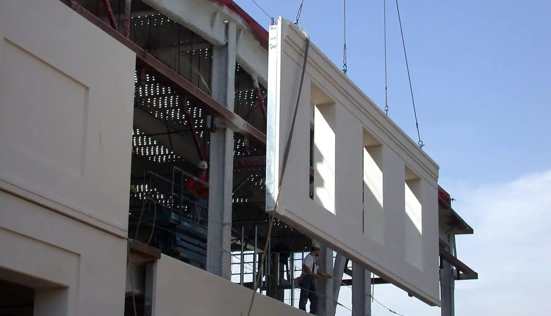
Precast construction has transformed the construction industry due to its speed, pace, accuracy, and repeatability. An effective and proper precast panel layout process is a significant phase within this procedure. As you work on architectural cladding or structural panels, the clear process of planning the layout would mean that coordination is better, the delays are minimal and the control of quality increases.
This blog post will guide you through the step-by-step precast panel layout, from the project’s inception to its final on-site delivery. As a contractor, structural engineer, BIM expert or detailer, this guide will offer some insights on how you can best plan around your precast panel layout to ensure project success.
Step 1: Understand the Project Scope and Requirements
An effective precast panel layout begins with a thorough comprehension of the entire design and makeup plan of the project. Teams need to be on the same sheet of paper before getting into the drawing or program, and there is a lot of that on the building requirements as they relate to what they need in functionality and what they want to look at and see.
Begin by consulting architectural and structural plans to see the purpose and use of each precast panel. Are the panels a form of artwork used solely to beautify or are they bearing a load? Do they have insulation built on? Which surface finish is included? These answers will not only affect the design, but also the manner in which the precast panel layout is to be organized.
This stage is establishing preconditions. Not getting the scope right in this regard can lead to things back firing later down the road to say the least, poor panel communication to the costly manufacturing defects.
Step 2: Establish Grid Lines and Reference Points
Construction accuracy starts with alignment, and your precast panel planning does not go against the norm. After determining the requirements of the project, they will be followed by defining a stable coordinate design by means of grid lines and reference points.
The skeleton on which the whole precast panel layout relies is the grid lines. These lines must be read off the architectural and structural drawings and translated into precast. You will also have to apply exact vertical datum levels in order to have panel elevations that are aligned floor-by-floor.
This is an important step in digital layout and erection on site. There is no point of reference that has been both clear and agreed upon, so the engineered position of the precast panel layout can drift between plan and reality, leading to a delay or misfit in position during installation.

Step 3: Break Down the Building Elevation into Panel Zones
Now that the structural grid is there, we can partition the elevations of the building into Zones of precast panel workability. Separation of the facade into rational parts guarantees the possibility of manufacturing and installation of both the panels, particularly in the situation of big or strenuous building faces.
Panel zoning takes into account:
- Structural bays and column locations
- Architectural symmetry and design breaks
- Transportation constraints (e.g., truck size and weight limits)
- Installation access, crane reach, and sequencing
- Location of window and door openings
Each precast panel layout zone must balance aesthetics with practicality. For example, maintaining consistent joint widths between panels not only improves visual appeal but also simplifies detailing and erection.
Common practices during zoning include:
- Defining vertical stacks or “panel runs” per floor
- Determining where horizontal breaks or expansion joints will occur
- Assigning unique identifiers to each panel for tracking and logistics
- Tagging corner, spandrel, and solid wall panels separately
By the end of this phase, your precast panel layout should present a clear visual roadmap showing how the building’s skin will be divided, transported, and assembled, paving the way for digital modeling, coordination, and fabrication.
Step 4: Create a Preliminary Precast Panel Layout Drawing
With zones established, structural alignment complete, one can go ahead and make the first precast panel layout drawing. Here, the mapping of arrangements starts in visual terms, coordinated with earnestness.
Still using tools such as Revit, AutoCAD, Tekla structures or any similar program that is compatible with BIM, your team can come up with an initial precast panelized layout that indicates panel placement and dimensions, panel ID numbers, and joint lines. This arrangement must act as a working and communication draft for the architects, engineers, and fabricators.
Important aspects to include in the preliminary drawing:
- Panel outlines with correct dimensions and shapes
- Assign unique panel IDs (e.g., E1-P03 for East Elevation, Panel 3)
- Color-coded panel types (insulated, spandrel, solid, etc.)
- Notations for joints, corner conditions, and embedded items
- Preliminary lifting and handling points (if already known)
The construction of this precast panel layout at an early stage also enables stakeholders to check the design intent and find problems prior to production. To change a digital model is far easier (and less expensive) than a fabricated panel.
It is at this point that the real work of collaboration between design and constructability starts, and where the precast panel layout transitions towards an actionable plan.
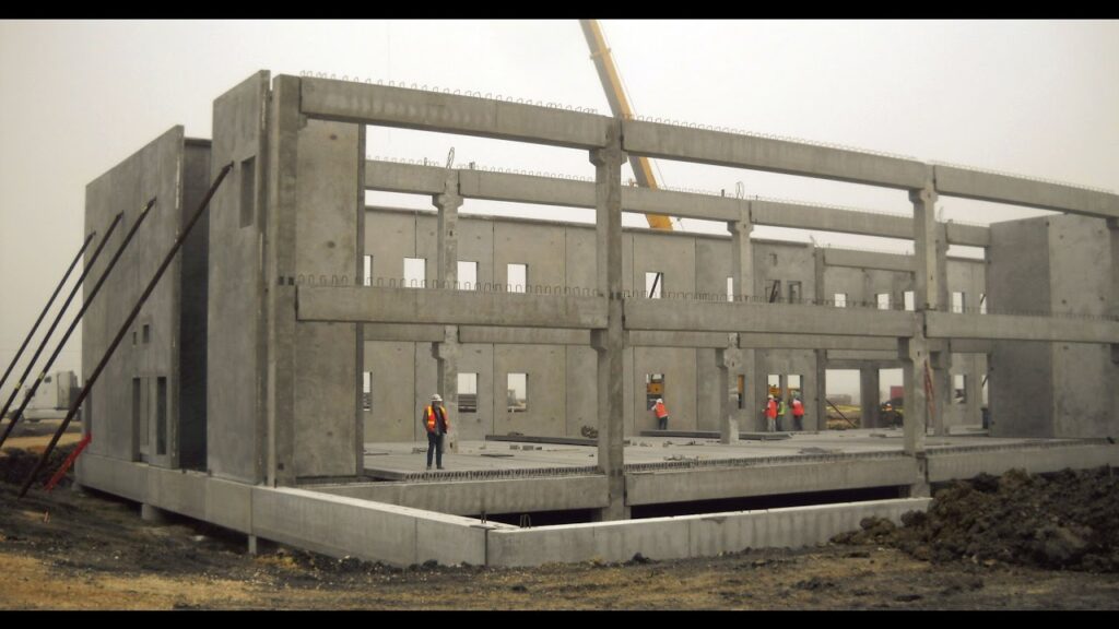
Step 5: Coordinate with Structural and MEP Disciplines
The effectiveness of any precast panels arrangement is so much related to the extent to which it interacts to the structural elements of the buildings, mechanical, electrical plumbing (MEP) systems. Failure to do this, even the best laid plan of how things should fall, can be seriously compromised in the field.
Active multidisciplinary coordination meetings are essential at this point to make sure your precast panel layout works in harmony with all the associated systems within a building. This would be most appropriate in a 3D BI,M whereby clashes may be identified graphically and addressed prior to fabrication.
Navisworks or BIM 360 clash detection tools can be really useful at this point. They are able to define any overlapping systems, misalignments or access conflicts before the initial panel is poured out.
Not only does a tight coordination of the structural and MEP elements with the precast panel layout eliminate rework and delays, but it can also enhance buildability and performance of the structure in the long term.
Step 6: Detail Panel Connections and Lifting Inserts
With the layout zones and the coordination checks being done, the next point of critical importance is to go deeper into the details of panel connection and handling systems. The layout of a properly designed and transportable precast panel layout should be structurally sound, not to mention safe to transport, and specification of anchorage, bracing, and lifting mechanisms. All panels must be fastened to the structural frame in an appropriate way and also be able to move through thermal expansion/contraction or seismic forces. Embedded plates, anchor bolts, dowels, and hardware appropriate to the purpose of the panel, as well as the location of the panel within an overall installation, should be detailed.
Structural connections are not the only accommodation that must be addressed in the precast panel layout design as movement of the precast panels out of the manufacturing facility and to the job site must also be considered when the lifting inserts and rigging systems are selected. These inserts have to be placed strategically depending on the center of gravity of such a panel and the angles of lifting keeping into consideration eccentric geometries.
Step 7: Review Tolerances and Adjust Joint Gaps
After detailing connections and lifting methods, the next step is to assess tolerances and fine-tune joint configurations within the precast panel layout. No matter how precise the fabrication or installation methods, some degree of variation is inevitable. That’s why accommodating these tolerances in the layout is essential to achieving a seamless façade and ensuring compatibility between adjacent building systems.
Joint gaps serve multiple purposes—they accommodate movement, prevent thermal bridging, and allow room for sealants and waterproofing materials. An optimized precast panel layout will ensure that joint widths are consistent across all elevations, contributing to both structural integrity and architectural consistency. Uneven gaps or misaligned edges can compromise aesthetics and lead to costly repairs.
Step 8: Finalize Shop Drawings and Erection Plans
Once tolerances and panel gaps are verified, the precast panel layout enters the documentation phase, where all planning is formalized into shop drawings and erection plans.
Shop drawings include:
- Panel dimensions and reinforcement details
- Location of embeds, lifters, and connections
- Marking plans showing where each panel goes on the structure
Simultaneously, erection plans detail the order in which panels should be delivered and installed. A well-sequenced precast panel layout minimizes crane movements, reduces panel handling, and avoids stacking delays on site.
Critical tasks at this stage include:
- Assigning panel numbers based on erection sequence
- Marking storage orientation and transport supports
- Preparing 3D lift diagrams and on-site rigging instructions
- Getting final approvals from engineers, contractors, and code officials
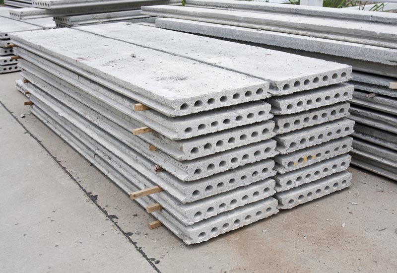
Step 9: Perform Quality Assurance and Digital Checks
Before any panels go into production, the precast panel layout must undergo rigorous quality assurance checks. QA checks include:
- Model audits: Ensuring all panel IDs, dimensions, and connections match across layout plans, shop drawings, and the 3D model
- Clash detection review: Running a final check in your BIM coordination software to spot late-stage conflicts
- Compliance checks: Verifying that all elements of the precast panel layout adhere to local codes, fabrication guidelines, and safety protocols
You may also generate digital reports or use software tools to simulate panel lifting, erection, and assembly. This helps prevent last-minute surprises and ensures a smooth transition to production.
Step 10: Monitor Layout Implementation On-Site
The final step in the workflow is to bring the digital precast panel layout into the physical realm during on-site installation. This stage demands strict alignment with the layout drawings and reference coordinates established earlier. Using tools like total stations, GPS layout systems, and laser levels, surveyors can pinpoint exact placement positions for each panel, ensuring alignment with the structural grid.
Installation crews rely on the precast panel layout to confirm that panels are oriented correctly, properly leveled, and securely fastened. Any deviations discovered on-site must be documented and resolved immediately to avoid cascading errors
Conclusion
Even though a well-structured precast panel layout workflow is crucial for a successful project, it’s nothing to worry about if each step is followed with precision. Simply put, our team ensures every detail—from grid setup to panel installation—is aligned with your project needs, guaranteeing the highest standards of safety and efficiency.
If you need help with your precast panel design or have any questions, contact Strand Construction & Engineering at (631) 805-3179. For more information, visit us at 490 Wheeler Rd, Suite 108, Hauppauge, NY 11788, conveniently located near the Long Island Expressway and Route 347.

