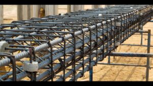
Reinforced concrete has long been a cornerstone of modern buildings and infrastructure. It balances the high compressive strength of concrete with the tensile capacity of steel bars. Yet, to achieve the best results, teams need precise plans. That is where rebar shop drawings become essential. These documents detail the shape, size, and placement of steel bars, ensuring each component meets design and safety requirements. In the following sections, we will examine how these drawings are created, why they matter, and how to avoid common errors. This text will also include a summary table of key terms and steps to improve field coordination.
By understanding the ins and outs of rebar shop drawings, construction managers, engineers, and detailers can reduce mistakes, save money, and meet strict building codes. Steel reinforcement is often the hidden hero of concrete elements. Without the correct data on how to arrange these bars, there is a higher risk of structural defects and costly rework. Teams need to know bar diameters, bending schedules, splice details, and other factors. If these details are off by even a small margin, site crews might face confusion, and the final product could fail to meet the project’s structural demands.
What Are Rebar Shop Drawings
Rebar shop drawings are specific documents prepared after reviewing the original structural and architectural plans. They focus on the steel bars that lie within concrete beams, slabs, walls, and columns. Unlike general design sketches, which show the overall building system, these shop drawings offer precise instructions on:
- Bar lengths and diameters
- Bending angles and shapes
- Overlap or splice details
- Concrete cover requirements
- Mark numbers for each bar
Because each bar’s placement can affect the load path and distribution, the accuracy of these plans is vital. Rebar shop drawings are not just for reference; they are the basis on which steel fabricators bend and cut bars. The exactness of these bends, overlaps, and labels simplifies on-site work, reducing the chance of misplacement.
These drawings also serve as a communication tool among architects, engineers, project managers, and contractors. By showing how each bar intersects or overlaps, they make conflict detection easier. If the mechanical or electrical trades have pipes or conduits in the same region, the detailer can adjust the layout to avoid clashes. This level of clarity helps keep the project on time and on budget.
Purpose of Rebar Shop Drawings
The primary goal of rebar shop drawings is to translate broad design concepts into workable instructions. Designers specify the required steel reinforcement, but these specs must be broken down into unique bar elements. Below are key objectives for these technical documents:
- Precision: By showing bar lengths, shapes, and placements, shop drawings reduce the possibility of errors.
- Compliance: Building codes demand correct reinforcement for safety. With shop drawings, detailers can confirm each bar meets relevant codes for anchorage, lap lengths, and cover.
- Coordination: Large projects involve many teams, such as formwork specialists, steel fixers, and MEP contractors. Quality drawings limit disagreements and rework by defining boundaries.
- Cost Management: When bars arrive pre-bent according to exact plans, it leads to lower labor costs, less material waste, and reduced on-site cutting or bending.
These factors highlight the true value of rebar shop drawings. Construction teams run fewer risks of missing important rebar details, which can cause expensive field changes or structural issues.
Key Elements in Rebar Shop Drawings
Each rebar shop drawing must contain crucial data to help field crews place bars correctly. The main elements are:
- Bar Schedule: A list of each rebar piece, including its shape code, bend angles, length, and diameter. This schedule usually appears in a table format, making it easier to manage the volume of materials on large projects.
- Mark Numbers: Each bar or set of bars has a unique label. This labeling helps site workers identify where each piece belongs.
- Bending Details: Detailed instructions on bends, hooks, and stirrups. These geometric forms ensure bars interlock properly to handle stress.
- Splice Information: Reinforced concrete often needs overlaps (or splices) to extend bar lengths. The drawings must show how these overlaps meet tension or compression requirements.
- Concrete Cover: The cover distance between rebar and the outer surface of the concrete. This detail protects steel from corrosion and fire damage.
Without these elements, rebar shop drawings lose their usefulness. Each piece of information must be correct and consistent with the project’s general structural plans.
Creating Accurate Rebar Shop Drawings
- Review Structural Drawings: Start by examining the main design documents. Locate all beams, columns, and slabs, noting the specified reinforcement. Pay attention to notes about load transfers, shear requirements, and potential tension zones.
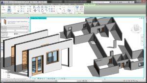
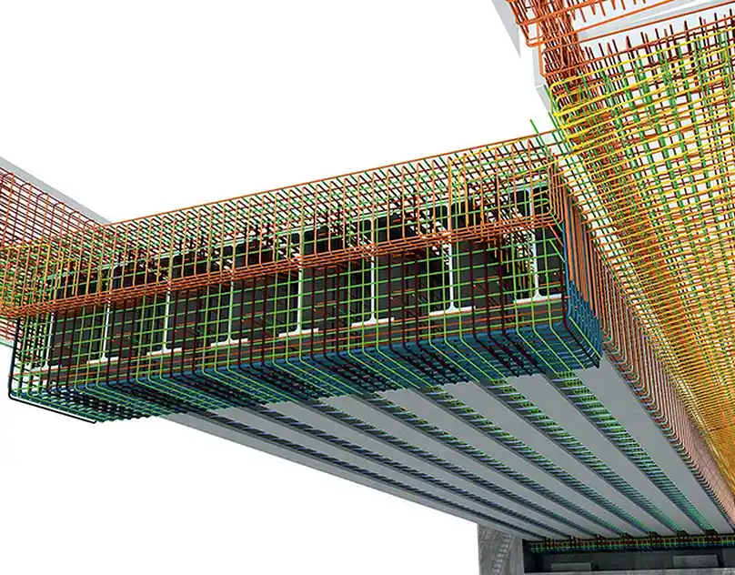
- Draft in Specialized Software: Tools like AutoCAD, Revit, or dedicated detailing programs help detailers produce precise shapes. They can save time by automating bar schedules and generating 3D views.
- Cross-Reference Codes: Depending on your region, local building codes define minimum lap lengths, cover, and other guidelines. Ensure each detail matches these standards to avoid rejections from inspectors.
- Coordinate with Other Disciplines: Always compare your final layout with mechanical, electrical, and plumbing drawings. If there is a clash, revise the bar arrangement accordingly.
- Seek Engineer Approval: After preparing the initial set, have the structural engineer review them. This step verifies that the drawings match the original design’s intent and the building’s load requirements.
When a project involves multiple floors or repeated sections, rebar shop drawings may follow a standard pattern for columns and beams. Detailers can create typical sheets for repeated elements, saving time while maintaining consistency.
Common Mistakes with Rebar Shop Drawings
Even with advanced software and careful planning, errors still happen. Some frequent issues include:
- Mismatched Bar Marks: If labels are inconsistent between the schedule and plan views, crews might install incorrect bars in key spots.
- Insufficient Overlaps: Underestimating lap lengths leads to weakened concrete elements that may crack under stress.
- Incorrect Cover: Placing rebar too close to the surface can lead to corrosion and reduced fire resistance.
- Poor Coordination: When rebar drawings conflict with mechanical or electrical lines, on-site workers may cut or bend bars in the field, compromising structural safety.
- Failure to Update: Projects evolve, and design changes happen. Not revising shop drawings leads to confusion and possible structural defects.
By recognizing these pitfalls, teams can refine their processes. Regular checks, open communication, and quality control help reduce rebar detailing mistakes.
Detailed Information Summary
Below is a concise summary of the primary items seen in rebar shop drawings and why they matter:
- Bar Labeling: Unique identifiers for each bar (e.g., B1, B2, T3). This practice ensures the correct bars end up in the right positions.
- Bending Schedules: Outlines the shape code and angles for easy fabrication and on-site clarity.
- Overlap Splices: Defines zones where bars overlap to extend the reinforcement’s total length. Correct splice design maintains tension capacity.
- Concrete Cover: Maintains a safe distance from the outer surface to prevent rust or structural weakness.
- Shape Codes: Standard codes define bar bends in a consistent manner, aiding fabricators and installers.
Summaries like this help teams recall the critical parts of rebar shop drawings. With so many details, it is easy to miss a key requirement or code reference. Having a quick checklist of terms and objectives allows any professional—whether an engineer, drafter, or site manager to confirm that the documentation meets expected standards.
Practical Tips for Rebar Shop Drawings
- Adopt Standardized Shapes: Consistency improves efficiency. By using standard bend shapes, you reduce confusion and speed up fabrication.
- Use Clear Notation: Label lap splice regions in bold or with dashed lines. Distinguish between top bars, bottom bars, and shrinkage bars.
- Include a Legend: A legend clarifies every symbol, from bar marks to hook angles. This guide reduces the learning curve for new team members.
- Confirm Dimensions: Double-check that all dimensions match the actual formwork size. An off-by-an-inch scenario can lead to major real-world issues.
- Consider On-Site Constraints: If the building site is crowded, plan for rebar storage and safe transportation. Large bars require special handling to avoid damage or accidents.
These points go beyond the raw creation of rebar shop drawings, focusing on real-world efficiency. By following them, teams can save time, prevent rework, and produce structures that match the design’s strength criteria.
Table: Terms and Descriptions
| Term | Description |
|---|---|
| Bar Mark | A unique identifier (like B1 or B2) assigned to each bar group for tracking and installation. |
| Lap Splice | The region where two bars overlap to form a continuous tension path in concrete. |
| Bending Schedule | A list showing each bar’s shape, angle, and length for easy fabrication and reference. |
| Concrete Cover | The distance from the outer concrete surface to the bar, protecting it from corrosion and fire. |
| Hook Angle | The bend at the bar’s end used for anchorage or to increase bond with concrete. |
| Shape Code | A standard reference to a particular geometry, helping detailers and fabricators maintain consistency. |
This table offers a quick look at vital terms that appear in rebar shop drawings. Each term represents a key aspect of steel reinforcement and needs to be checked thoroughly before finalizing any documentation.
Field Coordination for Rebar Shop Drawings
On-site work can be hectic, with different crews operating under tight deadlines. Field coordination for these drawings ensures the structural, architectural, and MEP teams cooperate:
- Pre-Installation Meetings: Gather all relevant subcontractors to discuss any possible clashes. Show them the rebar layout, focusing on congested areas like beam-column junctions or openings for mechanical ducts.
- Mock-Ups or Sample Areas: For complex parts of the structure, consider building a sample section to confirm bar placement. This test run helps detect potential errors.
- Monitoring and Inspection: As bars are placed, inspectors or engineers should compare the actual setup to the plan. If bars do not match the notes on lap length or spacing, the team can fix the issue immediately.
- Documenting Changes: If you must shift or modify any bar in the field, record that change. This record helps update as-built drawings and maintain accountability.
Through proper coordination, rebar shop drawings remain a reliable reference rather than a set of outdated plans on a project site. The best drawings lose their value if no one in the field applies them correctly.
Conclusion
Reinforced concrete relies on correct steel placement, making rebar shop drawings the backbone of a successful project. They ensure that the right bars go to the right places and meet the engineer’s design intent. By including bar schedules, splice details, bending instructions, and clear labeling, these documents simplify the work of fabricators and installers. When done well, they minimize errors, keep project budgets under control, and maintain high safety standards.
In a busy construction environment, rebar shop drawings bridge the gap between design theory and hands-on practice. A thorough review of each drawing, along with active communication among all trades, leads to smooth installations. Adding in a layer of quality checks and on-site inspections completes the loop, guaranteeing that the final structure aligns with the approved plans. For anyone involved in reinforced concrete construction, mastering these documents is a major step toward delivering sturdy, code-compliant outcomes.
By following the best practices outlined here, you can create, review, and apply rebar shop drawings with confidence. While they may appear technical at first, their clear data structure helps everyone understand exactly what to do. This clarity, paired with timely revisions and open dialogue, leads to fewer setbacks and more durable concrete elements. When each bar is properly placed and labeled, the project runs smoothly, saves money, and meets design goals.
FAQ 1: What are rebar shop drawings used for?
They are detailed plans that show the placement, bending shapes, and sizes of steel bars. Rebar shop drawings help construction teams avoid confusion and ensure all reinforcements meet design and safety standards.
FAQ 2: Why are rebar shop drawings crucial in large concrete projects?
They offer precise guidance on bar bending schedules, splice details, and cover requirements. Without rebar shop drawings, the risk of errors, material waste, and construction delays increases.
FAQ 3: Who is responsible for creating rebar shop drawings?
Typically, a specialized rebar detailer or drafting professional prepares rebar shop drawings. Afterward, an engineer or project manager reviews and approves them before fabrication begins.
FAQ 4: How do rebar shop drawings save time and money?
They reduce on-site guesswork and ensure accurate bar fabrication from the start. By having rebar shop drawings, you can avoid costly rework, extra labor, and schedule overruns.
FAQ 5: Where can I learn more about rebar before working with rebar shop drawings?
You can explore Wikipedia: Rebar for a basic overview of reinforcing steel. This helps you understand key terms and properties before reviewing your project’s drawings.