Precision is a must in structural steel construction. The robustness and the security of any structure with steel framing depend much on the strength of the connection of the parts in that building. This is where steel connection modeling comes into play. Whether it is high-rise buildings or industrial platforms, all the joints, either bolted and/or welded, should be properly designed and modelled to be durable, stable, and cost-effective.
Structural design and steel connection modeling are an intermediate between the creation of the structure and fabrication. It makes certain that all the welding details and bolt locations are well depicted in the digital model without the need to cut or join the material. Those connections that are poorly modeled may lead to clashes, constructability issues, and costly delays at the site.
The purpose of this guide is to introduce the fundamentals of modeling steel connections with emphasis on the welding and bolt planning critical issues. Continue to read these tips no matter whether you are a steel detailer, connection designer, or an engineer trying to make more than just accurate models.
What Is Steel Connection Modeling?
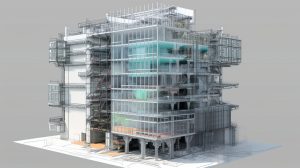
Steel connection modeling represents the connection between structural steel members as a digital model, with connections made between the structural steel beams, columns, and braces in a building or infrastructure development project. This involves the simulation of details of bolts, welds, plates, stiffeners, gussets, and other connection items in a three-dimensional space.
Developed steel connections are nowadays commonly modeled with BIM-based software such as Tekla Structures, Autodesk Advance Steel or SDS/2. They can have great detail modeling, constrained clash-detection, and tools to integrate with the manufacturing process.
The core goals of steel connection modeling are:
- To reflect real-world constructability and code compliance
- To avoid clashes between connected components
- To generate shop-ready details for welders and fabricators
- To enhance coordination between engineers, detailers, and fabricators
By incorporating connection logic early in the modeling phase, project teams can reduce errors, accelerate production, and improve the overall safety and efficiency of steel structures.
Common Steel Connections: Welded vs. Bolted

It is necessary to know the two main types of steel connections, welded and bolted, before indulging in the tips of modeling. They all apply differently, have their own advantages,s and modeling needs.
Welded Connections
Steel members in welded connections are fused together. Welding or fusion is typically done in a fabrication shop under controlled conditions. They are perfect for forming rigidity and load-sharing joints, which are seamless.
Advantages:
- Clean appearance
- Greater rigidity
- No need for bolt holes or hardware
Disadvantages:
- More labor-intensive
- Requires skilled labor and quality control
- Difficult to inspect and repair in the field
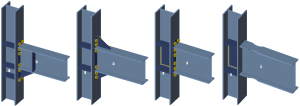
Bolted Connections
Bolted connections use high-strength bolts to join steel elements. They are widely used due to their simplicity, speed of installation, and ease of inspection.
Advantages:
- Fast assembly on-site
- Easier to inspect and disassemble
- Flexible for structural adjustments
Disadvantages:
- May require oversized or slotted holes
- More susceptible to vibration issues if not properly torqued
From a steel connection modeling standpoint, bolted connections demand attention to hole spacing, bolt sizes, and edge distances. Welded joints require correct symbol placement, weld lengths, and heat-affected zone considerations. Accurately modeling both types ensures your structure performs as intended and can be fabricated without issues.
Key Elements of Accurate Weld Plans
When it comes to steel connection modeling, weld plans are one of the most critical components. A weld that is improperly modeled can result in costly fabrication errors or structural weaknesses. Here’s how to ensure your weld plans are spot-on:
Use the Correct Weld Symbols
Follow standardized notation—such as AWS (American Welding Society) or ISO standards—for clarity and consistency. Incorrect symbols can lead to misinterpretation in fabrication drawings.
Represent Weld Types Properly
Model various weld types accurately:
- Fillet welds for T-joints and lap joints
- Groove welds for butt joints
- Slot and plug welds were required for load distribution
Account for Weld Accessibility
Ensure your model reflects actual welding conditions. Avoid designing joints that are impossible or unsafe to reach with welding equipment.
Include Heat-Affected Zones (HAZ)
For highly loaded joints, it’s important to consider the HAZ in your model. Some software allows visualization of these zones to check for weakening or potential overlap with other components.
Coordinate with Fabrication Standards
Always align your weld plans with the fabricator’s preferences and shop capabilities. Over-specifying welds can increase cost and production time.
In short, steel connection modeling must incorporate weld details not just for visual accuracy, but for practical constructability and performance assurance. Your goal is to ensure every weld modeled in 3D can be executed safely and effectively on the shop floor or job site.
Tips for Effective Bolt Modeling
In steel connection modeling, bolt connections are among the most common and crucial elements for constructability and field assembly. Accurately modeling bolt layouts ensures that what looks correct on screen translates into safe and seamless fabrication on-site.
Here are key tips to get bolt modeling right:
Select the Right Bolt Type and Grade
Use appropriate fasteners based on structural load requirements. For example:
- ASTM A325 or A490 high-strength bolts for structural framing
- Anchor bolts for column bases
- Expansion bolts for retrofit scenarios
Include bolt head type (hex, carriage, etc.) and finish (zinc-coated, galvanized) in the model for procurement accuracy.
Maintain Correct Spacing and Edge Distances
Follow engineering standards (AISC, Eurocode, etc.) for:
- Minimum and maximum bolt spacing
- Proper edge and end distances to prevent shear failure
- Row and column alignment for multi-bolt patterns
Model Holes, Washers, and Nuts Accurately
It’s not just about bolts—complete your model with:
- Bolt holes (including oversize, slotted, or countersunk)
- Washers and lock washers
- Nuts (standard or heavy hex)
This level of detail in steel connection modeling is essential for fabrication shops to avoid field modifications.
Perform Clash Detection
Use BIM tools to verify that bolts don’t clash with rebar, stiffeners, or nearby members. Even a minor clash can cause delays and rework during assembly.
Consider Installation Angles
Ensure bolts can be accessed with tools during erection. Avoid placing bolts in tight, unreachable corners unless special tools or access strategies are available.
Proper steel connection modeling of bolts ensures that every component aligns with engineering intent and shop capabilities, minimizing surprises during erection and inspection.
Using 3D Software for Better Steel Connections

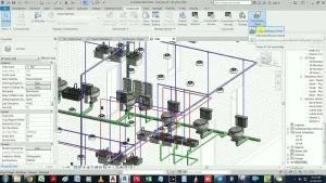
Modern steel connection modeling would not be possible without powerful 3D BIM tools. Platforms like Tekla Structures, Advance Steel, and SDS/2 have revolutionized how steel connections are designed, visualized, and coordinated.
Here’s how to make the most of your modeling software:
Automate Connection Templates
Many 3D tools offer smart connection libraries with pre-set configurations for clip angles, shear tabs, moment connections, and more. Automating standard details reduces time and human error.
Enable Real-Time Clash Detection
Advanced tools can automatically flag:
- Bolt clashes with stiffeners or beams
- Weld conflicts with access points
- Overlapping plates or material thickness mismatches
This allows modelers to resolve issues before they become field problems.
Integrate With Structural Analysis
Import forces and reactions from analysis software directly into your 3D model. This ensures that your steel connection modeling is not only geometric but structurally sound.
Generate Fabrication-Ready Outputs
These platforms can automatically create:
- Shop drawings
- DXF files for CNC machines
- Bolt lists and material take-offs
- Welding instructions and weld length summaries
By leveraging the full potential of your 3D software, you transform steel connection modeling from a drafting task into a smart, integrated design process—one that communicates intent clearly to every stakeholder, from engineers to fabricators.
Final Thoughts
Steel construction modeling can be as solid as the connecting joints that are used to keep them together. Be it a seismic resistant frame or a single beam column connection, the quality of your steel connection modeling will set the level of performance of your project, in determining how well your project is erected, both structurally and constructability-wise.
Characteristic of modern BIM tools is the ease of detailing, clash-free, and fabrication-ready connection models. Once you learn to sketch the bolts, the welds, plates, and connection rationality, you are doing your part to establish a rapport between virtual representation and the constructed reality. You save on RFIs, eliminate expensive field repairs, and simplify production- and yet come up with structures that have stood the test of time.