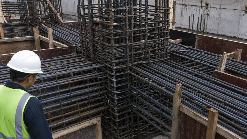
Rebar congestion often looks manageable on a drawing. Then the ironworkers begin assembling the cage.
Bars overlap at the lap zone. Stirrups compete with beam reinforcement. Couplers occupy the same space as embeds. A concrete pump hose cannot reach the intended location, and the vibrator has no clear path through the steel. The design may be structurally sound on paper, yet the reinforcement is difficult—or impossible—to build as detailed.
That is the practical problem of rebar congestion: too much reinforcement, too many components, or too little usable space in one area of a concrete member. It appears most often at beam-column joints, heavily loaded transfer elements, walls, deep foundations, splice zones, and connections with dense embedded items.
Congestion deserves attention before fabrication. Once bars arrive on site, every correction becomes slower, more expensive, and harder to coordinate.
What Is Rebar Congestion?
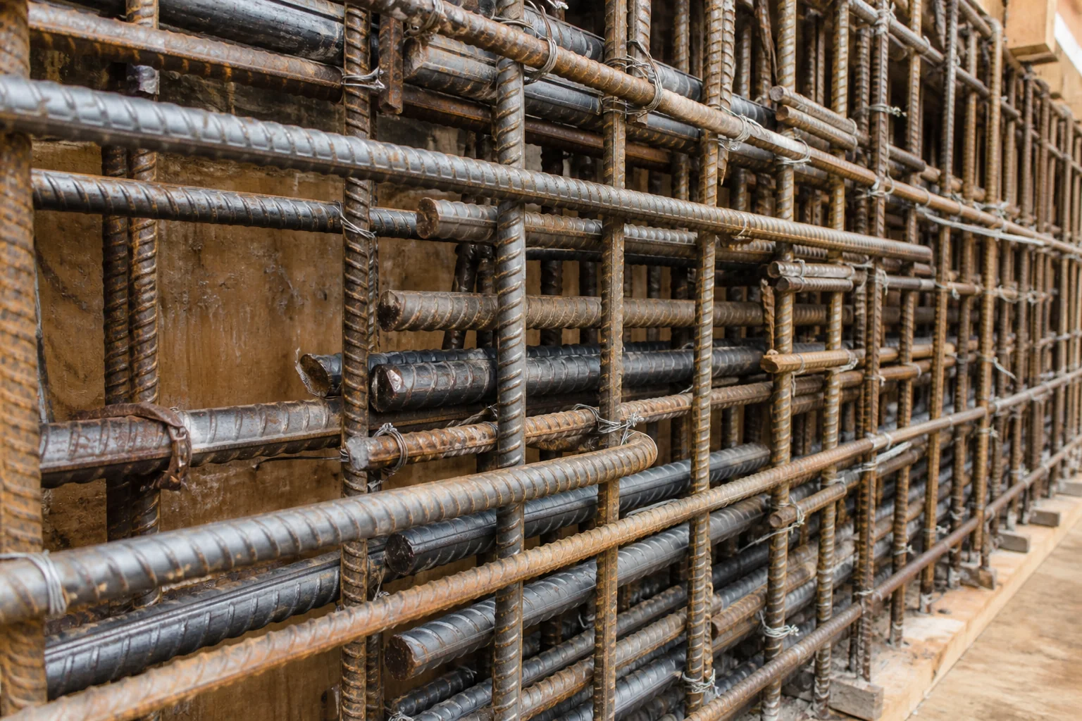
Rebar congestion occurs when the available clear space is insufficient for reinforcement placement, concrete flow, and proper consolidation. The problem involves more than bars touching in a model. A cage can satisfy nominal spacing requirements and still leave too little room for workers, concrete delivery, aggregate movement, or vibration equipment.
The American Concrete Institute notes that fresh concrete left with entrapped voids can become nonuniform, weak, porous, and poorly bonded to reinforcement. Dense steel makes that outcome more likely because it obstructs placement and consolidation paths. ACI guidance treats access and void reduction as basic conditions for achieving the intended concrete properties.
This is why a code-compliant reinforcement layout is not automatically a constructible one. The detail must work in three dimensions and in the sequence crews will use to assemble, place, and pour it.
What Causes Rebar Congestion?
Several decisions can quietly push a reinforcement layout past the point of practicality.
High reinforcement demand in a limited section
Heavily loaded beams, columns, walls, pile caps, and transfer slabs may require a large steel area inside a fixed concrete envelope. Adding more small-diameter bars can meet the calculated steel requirement while creating dozens of physical conflicts. Larger bars, higher-strength reinforcement, or a revised member size may provide a cleaner solution, subject to the engineer’s approval.
Lap splices concentrated in one location
Lap zones effectively double the reinforcement over part of a member. If bars from adjoining drawings terminate in the same region, the combined density may remain hidden until shop drawings are coordinated—or until installation begins.
Beam-column and wall intersections
Connections collect longitudinal bars, ties, stirrups, hooks, dowels, couplers, and anchorage zones in a small volume. Each system can look reasonable in isolation. Together, they form a knot of steel.
Uncoordinated embeds and openings
Anchor bolts, sleeves, conduits, cast-in plates, post-tensioning components, and MEP penetrations all consume space. A late opening can force bars into a tighter arrangement or interrupt the planned placement sequence.
Detailing in disconnected 2D views
Plans, elevations, and sections show selected slices of a structure. They do not always reveal how bar bends, hooks, laps, and adjacent cages interact through depth. A line that appears clear in one view may occupy the same physical space as another bar shown on a different sheet.
Design changes that do not reach every detail
A revised section size, opening, bar quantity, or embed location can leave downstream drawings out of sync. Small coordination gaps accumulate. The site team discovers the combined effect.
The Risks of Congested Reinforcement
Rebar congestion is often treated as an installation nuisance. That understates the problem.
Poor concrete placement and consolidation
Concrete must pass between bars and fill the form without leaving pockets. Dense reinforcement can block coarse aggregate, restrict the pump hose, and prevent a vibrator from reaching the full placement depth. ACI training material identifies reinforcement congestion as a contributor to poor consolidation and points to pre-pour review, mixture selection, and access planning as remedies. Its consolidation guidance also identifies splice zones and beam-column connections as common trouble spots.
Honeycombing, voids, and weak bond
Obstructed concrete flow can leave exposed aggregate, air pockets, or honeycombed areas. These defects may reduce bond around the reinforcement, increase permeability, and compromise durability. Repairs can address some surface defects, but severe voiding may require engineering evaluation or removal and replacement.
Bars displaced from their intended position
When a cage will not close, field crews may be tempted to move bars, reduce spacing, alter bends, or cut reinforcement. Even a well-meant adjustment can affect cover, development length, splice location, and force transfer. Unapproved field fixes create risk for the contractor and the engineer of record.
Slower installation and disrupted pour schedules
Congested cages take longer to assemble, inspect, and approve. Crews may need extra tying, temporary support, or re-sequencing. If the issue is discovered immediately before a pour, labor and equipment sit idle while RFIs move through the project team.
Fabrication waste and rework
Bars already cut and bent may not fit a revised arrangement. Replacement steel, expedited fabrication, handling, and schedule recovery all add cost. The most expensive clash is usually the one found after delivery.
Safety and quality-control pressure
Improvised installation in a tight cage increases handling difficulty and makes inspection harder. Congestion may obscure bar marks, laps, cover blocks, couplers, and ties. Under schedule pressure, quality problems become easier to miss.
How 3D Rebar Detailing Helps
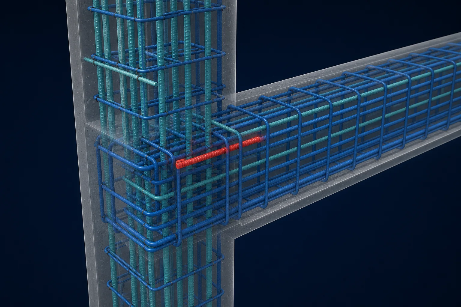
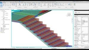
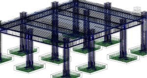
3D rebar detailing turns reinforcement from abstract lines into physical objects with diameter, bend radius, cover, shape, and location. The model exposes conditions that conventional drawings can hide.
It reveals clashes before fabrication
A detailed model can show bar-to-bar conflicts and interference with embeds, openings, structural steel, formwork, and MEP components. Detailers can inspect beam-column joints, lap zones, and complex anchorage from any angle. Realistic bar geometry improves clash prevention and allows earlier review in context.
It tests constructability, not only geometry
A clash-free model can still be hard to build. Good 3D detailing considers bar installation order, access for tying, coupler placement, cage stability, pump-hose routes, and vibrator access. It also tests whether prefabricated cages can be lifted and set as planned.
That distinction matters. Automatic clash detection finds overlapping objects. Constructability review asks whether people can assemble the reinforcement and place concrete around it.
It improves coordination across trades
A shared model gives structural engineers, rebar detailers, fabricators, contractors, and MEP teams one place to review crowded areas. Questions can be tied to a specific location instead of explained through marked-up screenshots from several sheets.
Early model review can identify congestion at lap locations before work begins. Model-based coordination also reduces drawing errors and unnecessary field cutting and bending.
It supports better detailing options
Once a congested zone is visible, the project team can evaluate alternatives such as:
- staggering lap splices rather than grouping them in one section;
- using mechanical couplers where approved;
- changing bar size, quantity, or spacing with engineering review;
- revising hook orientation or bar layering;
- relocating embeds and openings;
- increasing the member size where the design allows;
- planning concrete placement windows and vibrator access; or
- considering a more workable concrete mixture with the project’s concrete specialist.
The detailer does not make structural design changes independently. The model gives the engineer and construction team better evidence for choosing an approved solution.
It produces coordinated fabrication information
When drawings and bar bending schedules come from the coordinated model, revisions can flow through bar marks, quantities, shapes, and placement views. This reduces the chance that one sheet reflects a correction while another retains the old condition.
A Practical Workflow for Congested Areas

The best time to address congestion is before the reinforcing steel release.
- Model the full reinforcement zone. Include adjacent members, laps, couplers, embeds, openings, and relevant MEP items—not a simplified cage floating by itself.
- Run clash checks and inspect manually. Automated rules find direct interference; experienced detailers spot poor sequencing, inaccessible ties, and unrealistic placement conditions.
- Review high-risk locations with the project team. Prioritize transfer zones, joints, splice regions, thick mats, and anchor areas.
- Resolve issues through documented RFIs. Proposed changes should state the exact location, conflict, and possible options. Structural decisions remain with the engineer of record.
- Update every connected deliverable. Revise the model, shop drawings, bar lists, bending schedules, and coordination views together.
- Use the model for pre-pour planning. Installation crews can review bar sequence, access points, and concrete placement constraints before the cage is complete.
This process shifts coordination forward, where changes are still cheap.
3D Detailing Has Limits
A model does not repair poor communication or replace engineering judgment. Its value depends on accurate inputs, an agreed level of detail, current design information, and disciplined review. Clash detection settings also need care: overly loose tolerances miss problems, while overly strict rules bury the team in harmless warnings.
The useful deliverable is a constructible reinforcement package, not a polished model that nobody in the field can read.
Resolve Congestion Before It Reaches the Jobsite
Rebar congestion rarely begins in the field. It begins earlier, when individually reasonable decisions collide inside the same cubic foot of concrete.
3D rebar detailing makes those collisions visible while the team still has choices. Early coordination protects concrete quality, reduces fabrication changes, and gives installers a sequence they can follow. For complex reinforcement, that is a modest investment compared with stopping a scheduled pour.
Strand Consulting Corporation provides 2D rebar detailing, 3D rebar modeling, bar bending schedules, and BIM coordination for contractors, fabricators, and structural teams. Its as-built drawings can also document the final installed condition for handover and future work. Send us your drawings and project requirements to identify difficult reinforcement zones before steel reaches the site.
Frequently Asked Questions
What is rebar congestion?
Rebar congestion is a condition in which reinforcement and other embedded components leave insufficient space for practical bar installation, concrete placement, and consolidation. It commonly occurs at joints, lap zones, transfer elements, foundations, and heavily reinforced walls.
Can rebar meet code requirements and still be congested?
Yes. Minimum spacing, cover, and reinforcement requirements do not account for every installation sequence or concrete-placement constraint. A layout can satisfy design rules yet remain difficult to fabricate, assemble, vibrate, or inspect.
How does 3D rebar detailing prevent congestion?
3D detailing represents the actual diameter, bend, cover, and position of each bar. Detailers can detect conflicts, inspect dense zones from multiple angles, coordinate embeds and openings, and test placement sequences before fabrication.
Where is rebar congestion most common?
Typical locations include beam-column joints, lap-splice zones, pile caps, mat foundations, transfer slabs, shear walls, coupling beams, column heads, and areas containing many sleeves, plates, anchors, or post-tensioning components.
Who approves changes made to relieve rebar congestion?
The engineer of record must approve changes that affect structural design or contract requirements. The detailer can identify the conflict, model options, and prepare an RFI, but should not change bar sizes, quantities, development, or splice arrangements without authorization.